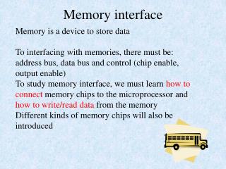
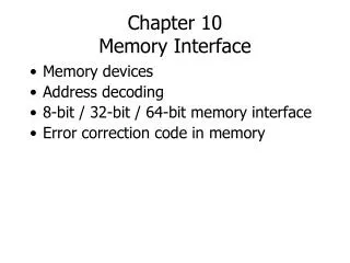
Chapter 10 Memory Interface
Chapter 10 Memory Interface. Memory devices Address decoding 8-bit / 32-bit / 64-bit memory interface Error correction code in memory. Memory Devices. Read-Only Memories ROM, PROM, EPROM, EEPROM Designed similarly to PLDs Read-Write Memories (RWM, RAM) SRAM, DRAM, Flash Memory

Chapter 10 Memory Interface
E N D
Presentation Transcript
Chapter 10Memory Interface • Memory devices • Address decoding • 8-bit / 32-bit / 64-bit memory interface • Error correction code in memory
Memory Devices • Read-Only Memories • ROM, PROM, EPROM, EEPROM • Designed similarly to PLDs • Read-Write Memories (RWM, RAM) • SRAM, DRAM, Flash Memory • DRAMs require the use of DRAM controllers to “refresh” the data stored in 1-transistorcells • Volatile vs. Nonvolatile • Does the data disappear when power is removed?
ROM SRAM DRAM WL WL BL WL WL BL BL BL PRAM Flash BL BL WL WL
I 1 oxide 2 “0” 1’ ” V1 V0 2’ [Chang, 2011] Memory Classification Non-volatile Memory Volatile Memory Charge Trap Polarization change Resistance change SRAM DRAM FLASH MRAM PRAM SONOS FRAM RRAM Interface or bulk Resistance changes Phase-dependent Resistance changes Magneto- Resistance changes Resistance-based Charge-based
[Source: K. Asanovic, 2008] bit lines word lines Col. 1 Col.2M Row 1 N Row Address Decoder Row 2N Memory cell(one bit) M N+M Column Decoder & Sense Amplifiers D Data Memory Architecture
Phase-change RAM (PRAM) bit line VCC current pulse source top electrode memory GST Vgate select TR metal SET RESET Amorphous = high resistivity Crystalline = low resistivity (Pictures from Hegedüs and Elliott, Nature Materials, March 2008)
RESET Fast quenching SET Slow quenching SET state = Low resistance RESET state = High resistance [Chang, 2011] Phase-change RAM (PRAM)
[Source: Samsung, 2000] NAND Flash Memory
Read-Only Memory (ROM) • Typical interface to a ROM • Figure 10-1 with WE included • Example of chip: Intel 2716 (2K x 8 = 16Kbit) • I/O pins shown in Figure 10-2 • A9-A0: address relation to memory size? • O7-O0: output data relation to memory organization? • CS, PD/PGM, Vcc, Vpp, GND • Timing specs shown in Figure 10-3 • Address to output delay, chip select to output delay, …
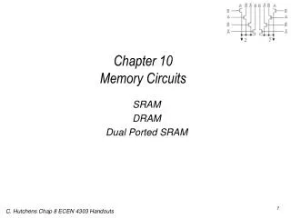
Static RAM (SRAM) • Example of chip: TMS4016 (2K x 8 = 16Kbit) • Pin-outs shown in Figure 10-4 (p. 333) • Bidirectional data lines: DQ8-DQ1 • Chip select: S • Output enable: G • Write enable: W • Power and ground: Vcc, Vss • Timing specs shown in Figure 10-5 • Parameter for read and write operations • Waveforms for read and write operations
6T SRAM • Several versions: 6T, 8T, 10T, 12T, … WL WL BL BL BL BL’ V DD 1 1 M M 1 3 V V2 ≈ VDD M DD 0.5Vdd 0.5Vdd 0 M 5 V1 ≈ 0 6 M M 2 4
Dynamic RAM (DRAM) • Example of chip: TMS4464 (64K x 4 = 256Kbit) • Pin-outs shown in Figure 10-7 • RAS and CAS used as row and column enables • Timing diagram shown in Figure 10-8 • Row and column address generation: Fig. 10-9 • Other Examples • Fig. 10-10: 41256 DRAM (256K x 1 = 256Kbit) device • Memory modules (small boards of memory chips) • 30-pin SIMM and 72-pin SIMM modules • 168-pin DIMM and RIMM modules • DRAM controller • Address multiplexing • Generation of DRAM control signals • DRAM refresh control CPU doesn't care about refresh Addr Addr bus DRAM controller Cntrl Cntrl bus DRAM Data Data bus
[B. Jacobs, 2002] tRCD CL tRP Simplified DRAM Operations BL Row Decoder Row Address WL • Three key commands • Row access (Activate or ACT): tRCD • Column access (RD/WR): CL • Precharge (PRE): tRP Sense Amplifier Column Address Column Decoder / Buffer Data In/Out
[Source: D. Lee, 2008] DDR SDRAM Banks Row Dec bank row • Three dimensions: bank, row, and column Row tRP tRCD Row buffer column Col Dec tCL Address Data • Memory access latency • E.g., 3-3-3: 3 cycles for each of ACT, RD/WR, & PRE RD D RD D RD D ACT ACT ACT PRE PRE PRE
DRAM RAS & CAS Timing RD D RD D RD D ACT ACT ACT PRE PRE PRE
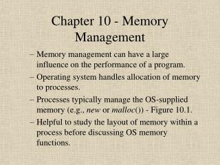
Address Decoding • Decoding of part of address output of CPU • Used to select a particular set of memory chips • Example shown in Figure 10-13 • Example of device used for decoding: decoder • Figures 10-14 and 10-15 • How to connect to memory chips with different organizations and sizes • E.g., 1M x 8, 2M x 4, 8M x 1, 16M x 1, etc.
With Decoder EPROM
Decoding with Programmable Devices (PROM or PLD) PROM
Memory Interface • Memory chip must be connected to CPU using the proper pins, and then send and receive signals with the proper timing behavior • CPU read and write timing specs specify the speeds that the CPU can read and write at • The CPU is typically faster than a memory device • To make the CPU operate slower, we must signal the CPU to “wait” for the memory device READY pin or other • Memory device connection and read/write timing specs • Different for each specific memory device
Memory Interface Examples • 8-bit memory interface (8088, 80188) • 16-bit memory interface (8086 – 80386SX) • 32-bit memory interface (80386DX, 80486) • 64-bit memory interface (Pentium – P IV) • Example: Figures in textbook
Memory Interface Circuit Design • What is the data width of the memory device used? • How many address lines are required by the memory device? • What range of addresses should the memory device respond to? • Ensure that no two memory devices drive different data onto the same data lines at the same time. • Are all memory timing requirements met?
8-bit Bus (512KB SRAM) 7FFFF buffer 2 40000 3FFFF 1 A19=0 1 00000 bidirectional buffer 2
More Complex Example: Memory Map & Interface Circuit
256KB SRAM(w/ Separated Byte Write) A17 A17 A17 A17 A17 A17 A17 A17
In-line Memory Modules for 8/32/64-bit Memory • One chip dedicated to parity bits SIMM (single in-line memory module) DIMM (dual in-line memory module)
[H. Lee, 2009] Rank • A rank is a set of memory chips sharing the address/control bus. Each rank is selected by CS (chip select) • One DRAM channel (identified by the control/data bus) can consist of multiple ranks
[H. Lee, 2009] Rank Examples • A rank of eight 8b memories can provide 64b memory
Error Control Coding • Example: (6,3) code
[Yang, 2010] ECC Example: Hamming Code • Encoding of [7,4] Hamming code – generator matrix, G
[Yang, 2010] ECC Example: Hamming Code • Parity check matrix, H
[Yang, 2010] ECC Example: Hamming Code • Syndrome and error detection
[Costello, 2006] ECC Example: Hamming Code • Syndrome and error detection