Download
1 / 24
240 likes | 342 Vues
Low temperature dissipation in coating materials.

E N D
Low temperature dissipation in coating materials S. Reid1, I. Martin1, H. Armandula3, R. Bassiri1, E. Chalkley1 C. Comtet4, M.M. Fejer5, A. Gretarsson6, G. Harry7, J. Hough1, P. Lu5, I. McLaren1, J-M.M. Mackowski4, N. Morgado4, R. Nawrodt2,S. Penn8, A. Remillieux4, S. Rowan1, R. Route5, A. Schroeter2,C. Schwarz2, P. Seidel2, K. Vijayraghavan5, W. Vodel2, A. Woodcraft1 1SUPA, University of Glasgow, Scotland. 2Friedrich-Schiller University, Jena, Germany. 3LIGO Laboratory, California Institute of Technology, USA. 4LMA, Lyon, France. 5Stanford University, USA. 6Embry-Riddle Aeronautical University, USA.7LIGO Laboratory, Massachusetts Institute of Technology, USA. 8Hobart and William Smith Colleges, USA.
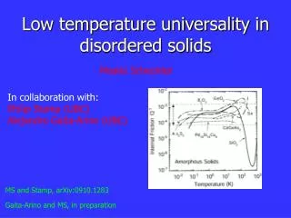
Overview • Introduction and experimental details • Measurements of the low temperature dissipation peak in Ta2O5 coatings • Possible dissipation mechanism in ion beam sputtered Ta205 • Effect of TiO2 doping on the loss in Ta2O5 coatings • Effect of annealing on the loss in Ta2O5 coatings • Comparison of dissipation in Ta2O5 and SiO2 films as a function of temperature • Magnetron sputtered SiO2 results from Jena University (slides courtesy of Ronny Nawrodt) • Preliminary results of Hafnia.
Mechanical dissipation from dielectric mirror coatings is predicted to be a significant source of thermal noise for advanced detectors. Experiments suggest Ta2O5 is the dominant source of dissipation in current SiO2/Ta2O5 coatings Doping the Ta2O5 with TiO2 can reduce the mechanical dissipation Mechanism responsible for the observed mechanical loss in Ta2O5 as yet not clearly identified Introduction GEO600 mirror suspension, with HR coating on front face. • Studying dissipation as a function of temperature of interest to: • Determine dissipation mechanisms in the coatings, possibly allowing dissipation to be reduced • Evaluate coating for possible use in proposed cryogenic gravitational wave detectors
Single layer coating samples for lowtemperature studies Thin silicon substrates used for coating Loss of silicon decreases at low temperature Coating will dominate the loss Samples etched from silicon wafers, with thicker clamping block to isolate cantilever from clamp 0.5 mm thick films deposited by ion beam sputtering, including (a) Ta2O5 doped with (14.5 ± 1)% TiO2 (b) un-doped Ta2O5 (c) SiO2 and (d) hafnia 34mm 48mm Coating applied here 500mm Titania doped tantala coatedsilicon cantilever in clamp uncoated silicon cantilever in clamp
Measuring coating loss • Bending modes of cantilever excited electrostatically, loss f(w) obtained from exponential amplitude ringdown • Loss of coating material calculated from losses of coated and un-coated cantilevers • Loss of coating material is given by: Typical amplitude of ring-down difference in loss between coated and un-coated cantilevers ratio of energy stored in cantilever to energy stored in coating
Mechanical loss measurements Comparison of the mechanical loss of the third bending mode (~1000 Hz) for a cantilever coated with Ta2O5 with 14.5 % TiO2, and an identical un-coated cantilever (in collaboration with Jena University)
Low temperature coating loss peak A dissipation peak at ~18-20 K observed in both TiO2-doped Ta2O5 (see figure) and pure Ta2O5
Most internal friction mechanisms may be thought of as relaxation processes associated with transitions between equilibrium states, and typically: where t is the relaxation time D is a constant related to height of peak Thermally activated processes follow Arrhenius equation: where t0-1 is therate factor and Ea is the activation energy for the process At the dissipation peak, wt =1 and hence Interpretation and analysis
Fitting to Arrhenius equation • This gives an activation energy associated with the dissipation peak in doped tantala of (42 ± 2) meV, and a rate factor of 3.3×10¹⁴ Hz.
(b) (a) Ta2O5 layer SiO2 layer Coating Structure • Convergent beam electron diffraction measurements (a) of a pure ion-beam sputtered Ta2O5 layer (see TEM image, (b)) shown only diffuse rings of intensity, confirming that the layer is amorphous.
Interpretation – double well potential • Low temperature dissipation peak in fused silica has similar activation energy (44 meV) • Oxygen atoms can undergo thermally activated transitions between two possible energy states in a double well potential • Width of the dissipation peak thought to be related to the distribution of Si-O bond angles in the sample • The dissipation mechanism in doped Ta2O5 may be similar, but requires further study potential barrier Potential energy stable Si-O bond angle stable Si-O bond angle Ea
Effect of doping Ta2O5 with 14.5 % TiO2 Comparison of dissipation peak in doped andun-dopedTa2O5 for 4th (left) and 5th bending modes (right). • Doping appears to reduce the height of the peak and slightly reduce the width of the peak
Effect of doping Ta2O5 with 14.5 % TiO2 Comparison of the dissipation of TiO2-doped and un-doped Ta2O5 • Doping reduces loss of Ta2O5 throughout temperature range
Effect of annealing • Heat treatment can reduce the dissipation in SiO2 possibly by changing distribution of bond angles • If dissipation mechanism in Ta2O5 is indeed similar to SiO2 it may be possible to modify characteristics of the dissipation peak by heat treatment • Ta2O5 known to crystallise above ~ 650 °C • Experiment currently underway to measure un-doped Ta2O5 coatings annealed at 300, 400, 600 and 800 °C • Initial results for 800 °C anneal
Effect of annealing temperature Loss at 1900 Hz of Ta2O5 annealed at 800 °C and 600 °C Losses similar close to room temperature effect of low T peak still visible in sample annealed to 800 °C • Large peak at ~ 80 to 90 K in coating annealed at 800 °C, perhaps due to onset of polycrystalline structure?
Comparison of SiO2 and Ta2O5 • Loss of ion beam sputtered SiO2 is significantly lower than loss of Ta2O5 between 10 and 300 K. scatter at higher temperatures possibly due to loss into clamp. Recent data suggests SiO2 loss of ~4×10⁻⁵ at room temperature.
Conclusions – Ta2O5 • Dissipation peak observed at ~ 20 K in both pure Ta2O5 and in Ta2O5 doped with 14.5 % TiO2 • Activation energy of dissipation process calculated to be 42 ± 2 meV (for doped coating). Possible dissipation mechanism is thermally activated transitions of the oxygen atoms, similar to that in fused silica • Some evidence that TiO2 dopingreduces the height of the dissipation peak in Ta2O5,in addition to reducing the loss at room temperature. • Ta2O5 coatings annealed at 800 °C display a large dissipation peak at ~90 K. • A full understanding of the dissipation mechanism may allow • Mechanical loss at room temperature to be further reduced • Reduction of loss at particular temperatures of interest for future cryogenic detectors • Ta2O5 has higher loss than SiO2 between 10 and 300 K
coating loss coated cantilever uncoated cantilever thermoelastic + residual gas loss Magnetron Sputtered Silica (400 nm) - Jena frequency: 2.8 kHz geometry: 50 mm × 8 mm × 70 µm Comparable level of observed loss associated with the magnetron sputtered silica coating at ~100 K to ion-beam sputtered silica. However, below 100 K no dissipation peak observed in magnetron sputtered silica
Magnetron Sputtered Silica (400 nm) - Jena • 464 Hz mode – resonance with clamping structure • Loss increases for all modes at low temperatures
Preliminary studies on HfO2 • New cryogenic setup in Glasgow: 500nm HfO2 coating on a silicon cantilever uncoated silicon cantilever thermal stresses in coating clearly observed in the bending of the silicon substrate
Preliminary studies on HfO2 and compared to Ta2O5 HfO2 at 960 Hz HfO2 at 336 Hz HfO2 at 56 Hz • Observed scatter in initial mechanical losses suggest energy coupling to clamp resonances for several of the resonant modes studied. Ta2O5 at 960 Hz HfO2 at 3310 Hz HfO2 at 1955 Hz
Preliminary HfO2 compared to Ta2O5 HfO2 at 960 Hz • At 100 K, the level of mechanical loss associated with both doped tantala and hafnia appear at a level f(w)coating ~ 4×10⁻⁴. • Below 100 K, the loss of tantala is observed to rise to a dissipation peak, whereas the loss of hafnia appears to decrease to below 3×10⁻⁴ at ~15 K. Ta2O5 at 960 Hz
Preliminary HfO2 compared to Ta2O5 • Preliminary results of the mechanical loss of Hafnia does not show a large dissipation peak at low T. • Note: the higher Young’s modulus of Hafnia should lead to lower thermal noise for the same f.d (loss-thickness product) – in the case of silicon optics (not true for other materials e.g. fused silica). • Initial room temperature studies on a multi-layer silica-hafnia coating on a fused silica substrate were found to be fhafnia=(5.7±0.3)×10-4. • However material properties for thin-film Hafnia are not well studied and any changes over bulk properties will change the results presented here. • The optical properties also require further investigation, where initial recent absorption studies of a multilayer silica-hafnia coating by Markosyan et al. (Stanford University) lie in the range 60-80ppm, which is considerably higher than required.