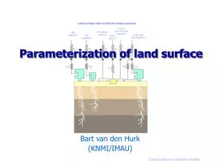
3D Surface Parameterization: Concepts and Techniques
Learn about mesh parameterization in 3D surfaces, including topology, mapping, distortion, and practical applications like texture mapping and remeshing. Discover how to deal with distortion and non-disk topologies.

3D Surface Parameterization: Concepts and Techniques
E N D
Presentation Transcript
3D Surface Parameterization Olga Sorkine, May 2005
Part OneParameterization and Partition Some slides borrowed from Pierre Alliez and Craig Gotsman
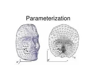
What is a parameterization? • S R3 - given surface • D R2 - parameter domain • s : D S 1-1 and onto
Isoparametric curves on the surface • One parameter fixed, one varies: • Family 1 (varying u): Lv0 (u) = s(u, v0) • Family 2 (varying v): Mu0 (v) = s(v0, v)
Analytic example: Parameters: u = x, v = y D = [–1,1][–1,1]. z = z(x,y) = –(x2+y2) s(x,y) = (x, y, z(x,y))
h 1 -1 Another example: Parameters: , h D = [0,][–1,1] x(, h) = cos() y(, h) = h z(, h) = sin()
Triangular Mesh • Standard discrete 3D surface representation in Computer Graphics – piecewise linear • Mesh Geometry: list of vertices (3D points of the surface) • Mesh Connectivity or Topology: description of the faces
Mesh Representation Geometry: v1 – (x1, y1, z1) v2 – (x2, y2, z2) v3 – (x3, y3, z3) . . . vn – (xn, yn, zn) v3 v2 vn v1 Topology: Triangle list {v1, v2, v3} . . . {vk, vl, vm}
Mesh Parameterization • Uniquely defined by mapping mesh vertices to the parameter domain: U : {v1, …, vn} D R2 U(vi) = (ui, vi) • No two edges cross in the plane (in D) Mesh parameterization mesh embedding
Mesh parameterization Parameterizations EmbeddingU Parameter domain Mesh surface D R2 S R3 s = U -1
Mesh parameterization s and U are piecewise-linear Linear inside each mesh triangle s U In2D In3D A mapping between two triangles is a uniqueaffine mapping
Barycentric coordinates C P A B
Mapping triangle to triangle s p3 q3 p1 q1 q2 p2
Only topological disks can be embedded • Other topologies must be “cut” or partitioned
Applications of parameterization • Texture mapping • Surface resampling (remeshing) • Mesh compression • Multiresolution analysis Using parameterization, we can operate on the 3D surface as if it were flat
Remeshing parameterization resampling
Distortion measures • Angle preservation • Area preservation • Stretch • etc...
Distortion minimization Texture map Kent et al ‘92 Floater 97 Sander et al ‘01
Resampling on regular grid Resampling problems Cat mesh Distorting embedding
Dealing with distortion and non-disk topology Problems: 1) Parameterization of complex surfaces introduces distortion. 2) Only topological disk can be embedded. Solution: partition and/or cut the mesh into several patches, parameterize each patch independently.
Partition – problems • Discontinuity of parameterization • Visible artifacts in texture mapping • Require special treatment • Vertices along seams have several (u,v) coordinates • Problems in mip-mapping Make seams short and hide them
Summary • “Good” parameterization = non-distorting • Angles and area preservation • Continuous param. of complex surfaces cannot avoid distortion. • “Good” partition/cut: • Large patches, minimize seam length • Align seams with features (=hide them)