SATELLITE COMMUNICATIONS
SATELLITE COMMUNICATIONS. BISHOY MOFIED OMAR SHAABAN VARTAN SHOUSHANIAN. 1. Outline. Introduction How satellite works History of satellites Satellite Frequency Bands Digital modulation schemes Satellite components Orbital altitudes GPS satellites Antenna Gain efficiency

SATELLITE COMMUNICATIONS
E N D
Presentation Transcript
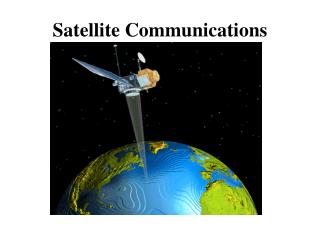
SATELLITE COMMUNICATIONS BISHOY MOFIED OMAR SHAABAN VARTAN SHOUSHANIAN 1
Outline • Introduction • How satellite works • History of satellites • Satellite Frequency Bands • Digital modulation schemes • Satellite components • Orbital altitudes • GPS satellites • Antenna Gain efficiency • Antenna Examples
History of Satellites(Read Only) • Early in October 1957 communications stations started picking up a regular beeping noise coming from space. • The signals were coming from Sputnik 1, the world's first man-made satellite by the soviet union. • At 1958, NASA successfully launched Explorer 1, the first American satellite.
History of Satellites(Read Only) • The first satellite picture of Earth came from NASA's Explorer 6 in 1959 • In 1963 , the world's first geosynchronous communications satellite NASA Syncom 2 was launched as Its earlier sister, Syncom 1, had been blown up on launch earlier that year, but the second version was a huge success. • Now a days 3,600 satellites are orbiting the earth out of 6,600 satellite launched the rest are part of the space debris
Advantages of Satellites • High channel capacity (>100 Mb/s) • Low error rates (Pe ~ 10-6) • Bit Rate (Bits/Sec) = BW * log2(1 + SNR) • Stable cost environment (no long-distance cables or national boundaries) • Wide area coverage (whole North America, for instance)
Disadvantages of Satellites • Expensive to launch • Expensive ground stations required • Cannot be maintained • Limited orbital space (geosynchronous)
How satellite works • A Earth Station sends message modulated in GHz range. (Uplink) • Satellite Receive signal and retransmit it back to the earth. (Downlink)
Satellite communication bands(read only) • Microwave frequency range 300MHz to 300GHz • Satellite frequency range 1GHz to 170GHz divided into bands with letters • Wide bandwidth • Line of sight required
Satellite communication bands L band 0.950 - 1.450 GHz GPS at 1.57542 GHz C band 3.7 - 4.2 GHz (Downlink) 5.925 - 6.425 GHz (Uplink) Ku band 11.7 - 12.2 GHz (Downlink) 14 - 14.5 GHz (Uplink) Ka band 18.3 - 18.8, 19.7 - 20.2 GHz (Downlink) 30 GHz (Uplink) V band 40 - 75 GHz 60 GHz allocated for unlicensed (WiFi) use 70, 80, and 90 GHz for other wireless
Satellite communication bands(read only) • Uplink and downlink
Phase Shift Key Modulation Binary phase-shift keying: Sinusoidal wave with 0 and 180 represent binary zero and one . Offset quadrature phase-shift keying : uses phase shift of 45,135,225,315 deg to represent 11,01,00,10 This doubles the channel bit rate
Offset quadrature phase-shift keying(read only) The I/Q modulator mixes the I signal with the carrier cosine wave, and it mixes the Q signal with the same carrier sin wave
Satellite system components There are many ways to build a satellite, but the key parts are always the same and these include: • Communication and processing system Antenna, Transceivers and On-board processor. • Propulsion system: Rocket motors and Thrusters. • Power System : Fuel tanks,Solarpanels,Batteries. 16
Satellite system components • Communication and processing -Transponder can either operate on bent pipe principle or regenerative principle Bent pipe:sending back to earth of what goes in with only amplification and a shift from uplink to downlink frequency. Regenerative:use on-board processing, to demodulate, decode, re-encode and modulated aboard the satellite. 17
Bent Pipe Principle Regenerative Principle
Satellite system components Regenerative Advantages • Reduce error rate (error correction) • Noise doesn't carry over • Increased system flexibility Disadvantages • Increased power consumption • Heavier payload • Difficult to change signal format (change modulation scheme) Bent Pipe Advantages • Reduced power and weight (simpler) Disadvantages • Inter modulation between carriers to be avoided • No error correction 19
Satellite system components -Transponder example (Bent pipe) 20
Satellite system components • Example Base station to user flow 21
Read only:Dual-band LNBs These will typically have two alternative local oscillator frequencies, for example 9.75 GHz and 10.6 GHz with the higher frequency option selected using a 22 kHz tone injected into the cable. Such an LNB may be used to receive 10.7 - 11.7 GHz using the lower 9.75 GHz LO frequency or the higher band 11.7 - 12.75 GHz using the higher 10.6 GHz LO frequency. LNB Frequency stability All LNBs used for satellite TV reception use dielectric resonator stabilised local oscillators. The DRO is just a pellet of material which resonates at the required frequency. Compared with quartz crystal a DRO is relatively unstable with temperature and frequency accuracies may be +/- 250 kHz to as much as +/- 2 MHz at Ku band. This variation includes both the initial value plus variations of temperature over the full extremes of the operating range. Fortunately most TV carriers are quite wide bandwidth (like 27 MHz) so even with 2 MHz error the indoor receiver will successfully tune the carrier and capture it . LNB supply voltages The DC voltage power supply is fed up the cable to the LNB. Often by altering this voltage it is possible to change the polarisation or, less commonly, the frequency band. Voltages are normally 13 volts or 19 volts.
Satellite system components • The propulsion system - large rocket motor and a smaller thruster rockets that keep the satellite at that location. -forces like the pressure of the solar wind, the effects of the Earth's and moon's gravity,.. -Attitude control through spinning gyroscopes. 25
Satellite system components Power System -Solar panel with battery • Power degrades over long time -Radioactive isotopes • Low power over long time -Fuel Cells • High power but needs resupply 27
TYPES OF SATELLITES (BASED ON ORBITS) • Geostationary or geosynchronous earth orbit (GEO) • Low Earth Orbit (LEO) • Medium Earth Orbit (MEO) 28
~35000 Km ~8000-16000 Km ~1600 Km 29
GEOSYNCHRONOUS EARTH ORBIT (GEO) • GEO satellites are synchronous with respect to earth. Looking from a fixed point from Earth, these satellites appear to be stationary. • Covers around 1/3 (120 degrees latitude) of the earth’s surface. • Three conditions which lead to a Geosynchronous satellites : • The satellite should be placed 37,786 kms (approximated to 36,000 kms) above the surface of the earth. • These satellites must travel in the rotational speed of earth, and in the direction of motion of earth, that is eastward. • The inclination of satellite with respect to earth must be 0. 30
GEOSYNCHRONOUS EARTH ORBIT (GEO) • Disadvantages of GEO: Northern or southern regions of the Earth (poles) have more problems receiving these satellites due to the low elevation above a latitude of 60°, i.e., larger antennas are needed in this case. • The transmit power needed is relatively high which causes problems for battery powered devices. These satellites cannot be used for small mobile phones. • The biggest problem for voice and also data communication is the high latency as without having any handovers, the signal has to at least travel 72,000 kms. • Transferring a GEO into orbit is very expensive 31
LOW EARTH ORBIT (LEO) SATELLITES • These satellites are placed 500-1500 kms above the surface of the earth. • As LEOs circulate on a lower orbit, hence they exhibit a much shorter period that is 95 to 120 minutes. • Each LEO satellite will only be visible from the earth for around ten minutes. 32
LOW EARTH ORBIT (LEO) SATELLITES • Disadvantage: The biggest problem of the LEO concept is the need for many satellites if global coverage is to be reached. (50–200 satellites) • One general problem of LEOs is the short lifetime of about five to eight years due to atmospheric drag and radiation from the inner Van Allen belt1. • The short time of visibility with a high elevation requires additional mechanisms for connection handover between different satellites. • the need for routing of data packets from satellite to if a user wants to communicate around the world. 33
MEDIUM EARTH ORBIT (MEO) SATELLITES • MEOs can be positioned somewhere between LEOs and GEOs,both in terms of their orbit and due to their advantages and disadvantages. Using orbits around 10,000 km • The system only requires a dozen satellites which is more than a GEO system, but much less than a LEO system. • These satellites move more slowly relative to the earth's rotation allowing a simpler system design (satellite periods are about six hours). 34
MEDIUM EARTH ORBIT (MEO) SATELLITES • Disadvantage : Again, due to the larger distance to the earth, delay increases to about 70–80 ms. the satellites need higher transmit power and special antennas for smaller footprints. 35
THE GLOBAL POSITIONING SYSTEM (GPS) • The Global Positioning System (GPS) is a worldwide radio-navigation system formed from a constellation of 24 satellites and their ground stations. • They are constantly moving, making two complete orbits in less than 24 hours. • These satellites are traveling at speeds of roughly ~11000 Km an hour. 36
THE GLOBAL POSITIONING SYSTEM (GPS) • The whole idea behind GPS is to use satellites in space as reference points for locations here on earth. • GPS satellites use a "triangulate," system where the GPS receiver measures distance using the travel time of radio signals. • By using triangulation, we can accurately measure our distance and find out position from three satellites position anywhere on earth 37
THE GLOBAL POSITIONING SYSTEM (GPS) • Even though the satellites positions are constantly monitored, they can't be watched every second. • The atomic clocks they use are very, very precise but they're not perfect. Minute discrepancies can occur, and these translate into travel time measurement errors. • The signal may not actually get to the ground station receivers first. It may bounce off various objects before it gets to the receivers. 38
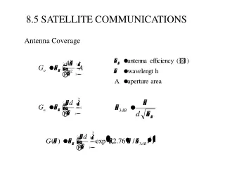
Antenna Design • To begin the derivation of the Friis Equation, consider two antennas in free space(no obstruction nearby) separated by a distance R, is power transmitted to transmitter antenna with Gain , while is received power to receiving antenna with Gain . • The Term Antenna Gain describes how much power is transmitted in the direction of peak radiation to that of an isotropic source. • Power density • Flux density 10 log() • dBW
POWER LOSS • =P x AE • = 4 / • = = + 20 log - 11.0 dB • is the efficiency of an antenna relates the power delivered to the antenna and the power radiated or dissipated within the antenna. • (path loss): 20 log() • dBW • = = x • Pr = Pt + Gt + Gr - LpdBW = + dB 40
Question #1. A C-band earth station has an antenna with a transmit gain of 54 dB. The transmitter output power is set to 100 W at a frequency of 6.100 GHz. The signal is received by a satellite at a distance of 37,500 km by an antenna with a gain of 26 dB. a. Calculate the path loss at 6.1 GHz. Wavelength is 0.04918 m. Answer: Path loss = 20 log() = 20 log ( 4 x37,500 x / 0.04918) dB Lp = 199.6 dB b. Calculate the power at the output port (sometimes called the output waveguide flange) of the satellite antenna, in dBW. Answer: Uplink power budget gives Pr = Pt + Gt + Gr - LpdBW = 20 + 54 + 26 – 199.6 = -99.6 dBW 41
2. A geostationary satellite carries a transponder with a 20 watt transmitter at 4 GHz. The transmitter is operated at an output power of 10 watts and drives an antenna with a gain of 30 dB. An earth station is at the center of the coverage zone of the satellite, at a range of 38,500 km.Using decibels for all calculations, find: a. The flux density at the earth station in dBW/m2 Answer: Flux density is given by F = 20 log [ PtGt / (4 ) ] dBW/m2 Hence for R = 38,500 km, f = 4 GHz,= 0.075 m F = 10 log Pt + - 10 log (4 ) - 20 log (38,500 x ) dBW / m2 = 10.0 +30.0 - 11.0 - 151.7 = -122.7 dBW / m2 b. The power received by an antenna with a gain of 39 dB, in dBW. Answer: Received power can be calculated from the effective area of the antenna aperture and the incident flux density, but since the antenna gain is given in dB, it is better to use path loss and the link budget. Path loss Lp = 20 log (4 R / ) = 10 log (4 x38,500x / 0.075) = 196.2 dB Downlink power budget gives Pr = Pt + Gt + Gr - LpdBW = 10.0 + 30.0 + 39.0 – 196.2 = -117.2 dBW Alternatively, the received power can be found from Pr = F + where is the effective aperture area of the antenna. Given G = 4 / = 39 dB, we can find from = G + 20 log - 11.0 dB = 39.0 – 22.5 –11.0 = 5.5 dB m2 Pr = -122.7 + 5.5 = - 117.2 dBW / m2 42