Booster Cavity: Parametric Study
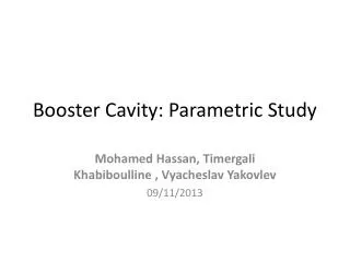
Booster Cavity: Parametric Study. Mohamed Hassan , Timergali Khabiboulline , Vyacheslav Yakovlev 09/11/2013. Specifications for Design of New Accelerating Cavities for the Fermilab Booster. Fermilab’s Booster Cavity. 2-Tuner. 1-Stem Connection. 3-Gap. 4-Taper.

Booster Cavity: Parametric Study
E N D
Presentation Transcript
Booster Cavity: Parametric Study Mohamed Hassan, TimergaliKhabiboulline , VyacheslavYakovlev 09/11/2013
Specifications for Design of New Accelerating Cavities for the Fermilab Booster
Fermilab’s Booster Cavity 2-Tuner 1-Stem Connection 3-Gap 4-Taper Cavity is divided into four areas to easily identify the cavity parameters Current Cavity dimensions will be marked in red, and all dimensions are in inches
Criteria of Comparison • Criteria of Comparison? • With eigen-mode simulation, the quality factor and energy (not the power) that would produce a required gap voltage could be calculated • Decreasing the energy needed for 55 kV gap voltage (increasing the Q) simply means less power loss inside the cavity thus less heating • These performance indicators will be calculated at two permeability values, namely; 8.4 and 3.0 that corresponds to the edge frequencies of the current booster operation ~Integral Average Simple Average
Stem Connection Parameters Rconn Increasing the radius of the stem conn would help in decreasing the overall power loss inside the cavity
Stem Connection Parameters Cont. Rconn_i Decreasing the radius of the stem inner conductor would help in decreasing the overall power loss inside the cavity
Tuner Parameters Rtunner1 Decreasing the radius of the tuner base radius would help in decreasing the overall power loss inside the cavity
Tuner Parameters Cont. Rtunner2 Decreasing the radius of tuner top radius would help in decreasing the overall power loss inside the cavity, though would decrease the bandwidth quite a bit (sorted out)
Gap Parameters R_Tube_Ring Gap Radius doesn’t have much effect on improving Q
Gap Parameters Cont. Rblend_Tube Gap Radius doesn’t have much effect on improving Q
Taper Parameters Rcone Decreasing Rcone would help in decreasing the overall power loss inside the cavity
Vivaldi Taper Tapercould be approximated as exponential (vivaldiequation) C=-0.04 (closest to current taper) Rconn Rcone Rpipe Lv Ls
Vivaldi Taper Cont. Rpipe=1.125”, Rcone=4.375”, Lv=28.12” Ls=5.5”, Rconn=2” Taper curve eq C=-0.04 C=-0.1 C=0.1 Steeper negative taper would help in decreasing the overall power loss inside the cavity
Vivaldi Taper Cont. Rpipe=1.125”, Rcone=4.375”, Lv=28.12” Ls=1”, Rconn=2.5”, Rtunner1=1” Taper curve eq Rtunner1 Rconn Ls
Vivaldi Taper Cont. Rpipe=1.125”, Rcone=4.375”, Lv=28.12”, Rconn=2.5”, Rtunner1=1” and changing Ls • Steeper negative taper would help in decreasing the overall power loss inside the cavity • However, it would come on the cost of sacrificing the bandwidth
Taper as a Matching Section? Rpipe=1.125 Rcavity=6 Rconn=2 Rconn_i=1 Zc=100Ω Zs=42Ω 14Ω 100Ω 42Ω/3 = 14Ω Three tuners in parallel are connected How to optimally match a 14Ω to 100Ω ?
Taper as a Matching Section Cont.? How to optimally match a 14Ω to 100Ω? Z1(z) Z0 Zl Z=0 Z=L Exponential Taper Klopfenstein Taper Triangular Taper
Taper as a Matching Section? • Standard tapers are used to minimize the mismatch between two impedances over wide frequency band however, we have a different goal
Tuner Ferrites: Other Possibilities • With all stackpole ferrites we project to have about 2 MHz shift upward in frequency band that would necessitates biasing the ferrites less to increase mu by about 15% to recover that frequency shift • Power loss will not decrease!, actually we project about 5% increase in power loss
Bore Radius Effect on the Cavity Performance Rpipe=2.5 Rpipe=1.625 Rpipe=1.125 • Increasing the beam pipe radius has a considerable effect on both the bandwidth and Q factor
Preliminary New Design Ref Cavity Design1 • Sacrifice for 2.4 MHz in bandwidth that will need to be compensated for by biasing less the ferrites • About 30% saving in power loss
Conclusion • Full parametric study have been carried out identifying the potential performance changes upon varying each cavity physical parameter • Preliminary new design is proposed • Better optimization is probably possible but needs more time
Booster Cavity: Proposed Measurements Mohamed Hassan, TimergaliKhabiboulline , VyacheslavYakovlev 09/11/2013
Tuner Stem Temperatures Temperatures are in deg F John Reid
Thermal Profile for Various Scenarios of Operation *Temperature in degC 55 KV, 15Hz 60 KV, 15Hz 55 KV, 7Hz
Simulated Temperature Profile for 55 kV, 15 Hz 55 kV, 15Hz Temperature [deg F] Temperature [deg F] All Copper Only • Under 55kV 15 Hz operation, we project that the highest temperature of copper is about 130 F, while it is about 204 F in Ferrties.
How to get a better comparison? • Run at a fixed frequency • Run without blower (is not included in the model) • Run to reach a steady state heating • Find an accurate way to measure the power loss and temperature • We should be able to compare then three vital quantities; quality factor, power loss, and temperature for a certain gap voltage (perhaps 10 kV, 20 kV) • Need to add as many as possible temperature sensors on each tuner • Repeat the measurements for several frequencies (37 MHz, 45 MHz, and 53 MHz)