Download
1 / 17
170 likes | 368 Vues
John Reid March 7, 2012. First Refurbished Booster RF Cavity for 15Hz. Booster RF Cavity removed from Station 8 Removed October 3, 2011 This cavity was picked to be first for the following: One of the lowest for radioactivity. Cavity had a suspected small vacuum leak.

E N D
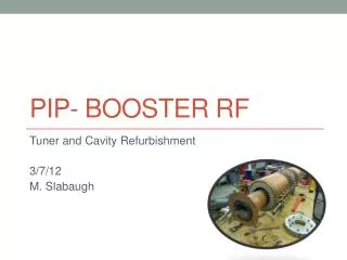
John Reid March 7, 2012 First Refurbished Booster RF Cavity for 15Hz
Booster RF Cavity removed from Station 8 • Removed October 3, 2011 • This cavity was picked to be first for the following: • One of the lowest for radioactivity. • Cavity had a suspected small vacuum leak. • Cavity had performance issues when cold. • Shipped cavity to MI-60 for initial testing before disassembly. • Cavity moved into cave at MI-60 for high power testing. • Cavity leak checked and found to have a vacuum leak on upstream end flange. • Temporary repair was performed to allow cavity to under go initial testing at 15Hz. • Cavity run at 15Hz with reduced gradient to measure temperature rise of critical components. • Stem temperature > 200 F in 15 minutes running John Reid
Leaking Cavity End Flange John Reid
Standard Ferrite Tuner John Reid
Cavity End Cut Open John Reid
Bad Tuner Stem Connection John Reid
Burnt Tuner Cone John Reid
Burnt Fingers on Cone John Reid
Inside Center of Cavity John Reid
Anode Blocking Capacitor John Reid
Anode Blocking Capacitor John Reid
Std Operating Waveforms Phase Det Error – Light Blue Anode Prog – Purple – 23kVpk RF Gap Envelope – Drk Blue PA Screen I - Green John Reid
Std Operating Waveforms FBI – Yellow FBV – Green Plate I - Blue John Reid
Stem Temp vs Anode Voltage John Reid
Parameters at 23kV anode voltage @15Hz for 12 hours. • Gradient ~52.9kV peak accelerating voltage • Blocking capacitor temperature = 140 F • High voltage filter chokes – 150 F • Inside drift tube temperature = 145 F • Drift tube temperature = 140 F • Beam tube temperature (on Mu-metal shield) = 150 F • Cavity outer shell temperature by PA = 114 F • Ceramic window outer ring temperature = 106 F • Ferrite Power removed to water = 5.9kW per tuner • Back tuner stem temperature = 165 F • Front tuner stem temperature = 175 F • Bottom tuner stem temperature = 179 F • Cavity vacuum = 1.17 x 10⁻⁷ Torr John Reid
Conclusions • Cavity does operate at 15Hz full gradient, BUT • Need to reduce stem temperatures • Elevated temperatures are in part due to a very small gap (0.001 to 0.002 inches) on stem vertical connection to center section. • Going to make a 0.005 inch tin gasket to help in sealing this high rf current connection. • Want to do longer continuous running starting as soon as gaskets are installed. • Consider installing cavity back in Station 8 before the end of March. John Reid