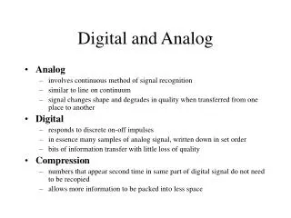
Analog And Digital Interfacing
Analog And Digital Interfacing. Big Picture. Physical world. Other Systems or ICs. Digital Communication. Analog Interfacing. MSP430. Sensors. A device that converts a physical phenomenon into an electrical signal Physical phenomenon light, temperature, humidity, pressure, and etc.


Analog And Digital Interfacing
E N D
Presentation Transcript
Big Picture Physical world Other Systems or ICs Digital Communication Analog Interfacing MSP430
Sensors • A device that converts a physical phenomenon into an electrical signal • Physical phenomenon • light, temperature, humidity, pressure, and etc. • Electrical signal • resistance, capacitance, current, voltage, and etc. • Maps a physical phenomenon change to a electrical signal change
Signal Path Produce a proper output voltage level Signal Conditioning (if necessary) Sensors • Amplification • Filtering Analog to Digital Conversion (ADC) • Light • Temperature • Acceleration • Humidity • Pressure • etc. • Resistance • Capacitance • Current • Voltage • etc. 10011101 Convert to voltage Converts voltage to digital number
Sensors We Have • Raw sensors • Produce raw electrical signal • Signal conditioned sensors • Have some signal conditioning circuit • Produce analog output • Mostly Voltage • Sometime Current
Sensors We Have • Digitalized sensors • Have some signal conditioning circuit • Convert analog to digital internally • Provide digital output
Our Focus Produce a proper output voltage level Sensors Signal Conditioning (if necessary) Sensors • Amplification • Filtering • Light • Temperature • Acceleration • Humidity • Pressure • etc. Analog to Digital Conversion • Resistance • Capacitance • Current • Voltage • etc. 10011101 Convert to voltage Converts voltage to digital number • We are not going to talk about signal conditioning • You can find many sensors that are signal conditioned and provide a proper analog output, or even digitalized • We will focus on how to understand these signal conditioned sensors and get the output we want
Some Raw Sensors • Temperature Sensors • Thermistors • Temperature-sensitive resistor • RTDs (resistive temperature devices) • Temperature-sensitive resistor • Thermocouples • Temperature => voltage (mV) • Pressure sensors • Piezoresistive • Resistancechange with applied pressure
Photodiodes • Light => current • Generate current proportional to light density
Photodiodes • Two on Taroko • S1087: for visible range • S1087-01: for visible to IR(infrared) range
Signal Conditioned Analog Output • Proximity sensor • Sharp GP2D120XJ00F • Analog voltage output • Accelerometer • ADXL330 3-axis accelerometer • Analog voltage output • Industry standard analog output • Flow sensors, pressure sensors, gas sensors, etc. • 4~20 mA, 0~5 V, 0~10 V
Proximity Sensor • Sharp GP2D120XJ00F • Output voltage proportional to the reflection distance • Measure range: 30 cm
Accelerometer • Analog Device Inc. ADXL330 • Output voltage proportional to the acceleration • Measurement range: +/- 3.6 g
Gyro • Invensense ISZ-500 • Z axis gyro, ±500 °/sec • 2.0 mV/°/sec • Invensense IDG-500 • X/Y axis gyro, ±500 °/sec • 2.0 mV/°/sec • Invensense IMU-3000 • 3-axis gyro, (±250, ±500, ±1000, ±2000) °/sec • I2C interface
Industry standard analog outputs • Many industrial instruments provide analog outputs • 4~20 mA current loop • Most commonly used • The instrument produce a current, range from 4 mA to 20 mA • Physical measured quantity linearly maps to this current range • Others • 0 ~ 5 V • 0 ~ 10 V
4~20 mA current loop • Examples • Measure temperature: 0 ~ 100 oC • Measure flow speed: 0 ~ 50 m3/h Measurements 0 oC 50 oC 100 oC Current Output 4 mA 12 mA 20 mA Usually this range is user configurable Measurements 0 m3/h 25 m3/h 50 m3/h Current Output 4 mA 12 mA 20 mA
How to Convert to Voltage • Add a resistor
Digitalized Sensors • Ultrasound sensors • SRF10 • Interface: I2C • Temperature and Humidity Sensor • SHT11 • Interface : manufacturer defined
Digitalized Sensors • Magnetometer • SFE MicroMag 3-Axis • Interface : SPI • Applications: detecting vehicles • Digital compass • Hitachi HM55B • Interface : UART
Digitalized Sensors • GPS • Garmin GPS18 • Interface : UART • Image sensor • ST VS6451 • Interface: I2C
Understand The Analog Sensors • Most important goal • Obtain the relationship between voltage and the physical phenomenon quantity you want to measure • Transfer function • Understand the characteristics and limitation of the sensors
Sensor Characteristics Definitions • Transfer Function • Relationship between physical quantity and output voltage • Sensitivity • Ratio of change between physical quantity and output voltage • Accuracy • Largest expected error • Linearity • How linear the transfer function is • Noise • In real world, signal are usually coupled with noise • Resolution • minimum detectable signal fluctuation • Bandwidth • response times to an instantaneous change in physical signal
Transfer Function Ratiometric? Output voltage is a ratio of supply voltage • ADXL330 accelerometer From ADXL330 datasheet It means when supply voltage Vs is 3 V, if the acceleration increase by 1 g, the output voltage will increase 330 mV (typical) It means when supply voltage Vs is 3 V, if the acceleration is 0 g, the output voltage will be 1.5 V (typical) Transfer function: Voltage (V) = 1.5 + (0.3 * acceleration (g) )
Transfer Function • Proximity sensor: Sharp GP2D120XJ00F Transfer function Voltage (V) = f(Distance (cm)) • Not a linear function • Check datasheet • if the manufacturer has provided • Table mapping • Approximations • By a few straight lines • Curve fitting
Transfer Function • Photodiode: S1087, S1087-01 Transfer function Voltage (V) = f(light level(lx)) Calculate by yourself From Taroko Schematic Step 2: find the relationship between current and the voltage at ADC4 (V = IR) Step 1: find the relationship between light level and current
Sensitivity • ADXL330 accelerometer • Sharp GP2D120XJ00F • Not a constanst • Photodiode: S1087, S1087-01 • (Current)/(light level)
Linearity Sharp GP2D120XJ00F Photodiode: S1087, S1087-01 BAD GOOD GOOD ADXL330 accelerometer
Bandwidth • How fast the next valid output ready When power up, you have to wait for 52.9ms to get a first valid output. You have to wait another 47.9ms to get the second one. • Proximity sensor: Sharp GP2D120XJ00F For the module we will use, the filter capacitor is 0.1 uF. It means the accelerometer module can have at most 50 different read-outs in one second ADXL330 accelerometer
T Analog to Digital Conversion • Periodically read the voltage of the signal • Convert to a digital number • Represent the voltage of the signal • At the sampling time
Analog to Digital Converter (ADC) • ADC takes two inputs • Voltage reference (dynamic range) • Range of voltage that it can measure • It has a limited range • Sensor signal • Resolution • How many bits the ADC can output • Sample Rate • How many sample it can takes in one second • For MSP430F1611, it is about 200 ksps That’s why we need signal conditioning to produce a proper voltage output
Resolution • You heard 10-bit ADC, 12-bit ADC, 16-bit ADC • What are they? • Number of bits the ADC can output • This is a 4-bit ADC • [0,0.1) V -> 0000 • [0.1,0.2) V -> 0001 • [0.2,0.3) V -> 0010 • [1.5,1.6) V -> 1111 • If it is a 6-bit ADC • [0,0.025) V -> 000000 • [0.025,0.05) V -> 000001 • [0.05,0.075) V -> 000010 • [1.575,1.6) V -> 111111
Discretization • 1 bit 2 possible values • 2 bits 4 possible values • 8 bits 256 possible values • 12 bits 4096 possible values • 16 bits 65356 possible values : : • N bits 2N possible values } Quantization error
Dynamic Range • Range of signal amplitudes which the ADC can resolve Max possible value Min possible value
Voltage reference • Input voltage compares to the voltage reference • Ratio of (input voltage)/(voltage reference) determines the output number • Two voltage references • Positive voltage reference (Vref+) • Negative voltage reference (Vref-) • In this figure, Vref+ = 1.6V; Vref- = 0 V • [0,0.1) V -> 0000 • [0.8,0.9) V -> 1000 • [1.5,1.6) V -> 1111 • If we change the Vref+ = 3.2V; Vref- remains 0 V, then • [0,0.2) V -> 0000 • [1.6,1.8) V -> 1000 • [3.0,3.2) V -> 1111
About Voltage Reference • Voltage reference can by internal or external • Many ADCs have internal voltage reference integrated • Unstable Voltage reference will affect the accuracy of the ADC • Minimum, Maximum • If input voltage > Vref+, always output 1111 • If input voltage < Vref-, always output 0000 • Voltage Reference cannot exceed power supply voltage
Dynamic Range • Too low • Good resolution • Saturation • Too high • Poor resolution • No saturation
Detectable Voltage Change • Voltage reference + Resolution • Define the detectable voltage change • Detectable voltage change = ((Vref+) – (Vref-))/(2^resolution) • Examples • Vref = 1.6V, Resolution = 4-bit • Vref = 3.2V, Resolution = 4-bit • Vref = 1.6V, Resolution = 6-bit 1.6/(2^4) = 0.1 V 3.2/(2^4) = 0.2 V 1.6/(2^6) = 0.025 V
Sample And Hold • There is a sample-and-hold circuit before A/D conversion • Mostly integrated in the ADC chip • When no conversion, switch S1 is open • When a conversion start • S1 closed • Input signal charge C1 • S1 open, C1 holds the value of input signal • A/D conversion • Sample-and-hold time • Time between S1 close and re-open • If it is too short • C1 will not fully charged (error)
ADC Clock • ADC needs a clock • For sample-and-hold and the A/D conversion
ADC on Taroko • 12-bit on-chip ADC in MSP430 • Voltage reference • Internal Vref: 1.5V, 2.5V • No external Vref on Taroko • User configurable combination for Vref+ and Vref- • Sample rate • Approximate 200 ksps • User configurable sample-and-hold time • User configurable clock sources
An Example: ADXL330 • ADXL330 3-axis accelerometer • Transfer function: V = 1.5 + (0.3 * g)
An Example: ADXL330 • Taroko ADC setting • Resolution: 12-bit • Voltage reference • Vref+ = 2.5 V • Vref- = 0 V • Conversion formula • NADC is the output number • For our setting
An Example: ADXL330 • Transfer function: V = 1.5 + (0.3 * g) • Conversion formula • When the acceleration is 0 g • V = 1.5 • NADC = 2457 • When the acceleration is 1.5 g • V = 1.95 • NADC = 3194 • When NADC = 1784, what is the acceleration? • When NADC = 2635, what is the acceleration?
Real World Design • In practical design, there are always errors • Noises • Power supply noise • Digital circuit noise • RF noise • Devices noise • Devices Tolerances • 5% resistor, 1% resistor • 10% capacitor • etc. • Temperature drift • Devices characteristics change when temperature change • Two very simple methods to deal with two very common errors
First Type of Errors • Noise • Dynamic • ADXL330 at 0 g (1.5V) • Sample at S1 -> ok • Sample at S2 -> it is 0.333 g • Sample at S3 -> it is -0.333 g • Solution • Average • (S1 + S2 + S3)/3 = (1.5+1.6+1.4)/3 = 1.5 1.6V 1.5V 1.4V S1 S2 S3
How Many Samples • How many samples needed to average • Depends on your requirement • Suggestion: factor of 2 (2N) • Take 10 samples and average • Take 16 samples and average Division => slow Total += Si; //(i=1,…,10) Result = Total/10; Bit shift => fast Total += Si; //(i=1,…,16) Result = (Total>>4);
Cautions! • Is the Total large enough to hold the summation • Max possible Total = 4096*16 = 65536 • Total should be at least 16-bit unsigned int • IMPORTANT!! • int in IAR for MSP430 is 16-bit long Total += Si; //(i=1,…,16) Result = (Total>>4);
Second Type of Errors • Offset • Static • For example: ADXL330 • For A accelerometer, 0 g output maybe 1.5V • For B accelerometer, 0 g output maybe 1.54V 30% of ADXL330, 0 g output is 1.53V 4% of ADXL330, 0 g output is 1.5V From ADXL330 datasheet
Calibration • Maintain a calibration constant, adjust the offset error • ADXL330 with calibration • Transfer function: V = (1.5 + Ccal) + (0.3 * g) • Ccal is calibration constant • For A accelerometer, 0 g output is 1.5V • Ccal = 0 • If NADC = 2879, acceleration should be 0.859 g • For B accelerometer, 0 g output is 1.54V • Ccal = 0.04 • If NADC = 2879, acceleration should be ?? G