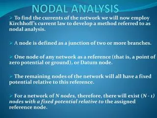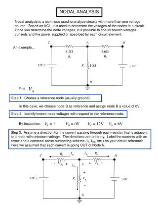
Nodal Analysis
Nodal Analysis. Discussion D2.3 September 2006 Chapter 2 Section 2-7. Nodal Analysis. Interested in finding the NODE VOLTAGES, which are taken as the variables to be determined For simplicity we start with circuits containing only current sources. Nodal Analysis Steps.

Nodal Analysis
E N D
Presentation Transcript
Nodal Analysis Discussion D2.3 September 2006 Chapter 2 Section 2-7
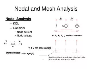
Nodal Analysis • Interested in finding the NODE VOLTAGES, which are taken as the variables to be determined • For simplicity we start with circuits containing only current sources
Nodal Analysis Steps • Select one of the n nodes as a reference node (that we define to be zero voltage, or ground). Assign voltages v1, v2, … vn-1 to the remaining n-1 nodes. These voltages are referenced with respect to the reference node. • Apply KCL to each of the n-1 non-reference nodes. Use Ohm’s law to express the branch currents in terms of the node voltages. • Solve the resulting simultaneous equations to obtain the node voltages v1, v2, … vn-1.
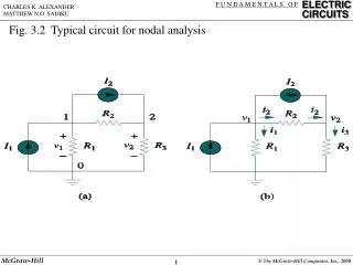
Example Select a reference node as ground. Assign voltages v1, v2, and v3 to the remaining 3 nodes.
Example Apply KCL to each of the 3 non-reference nodes (sum of currents leaving node is zero). Node 1: Node 2: Node 3:
Example Now express i1, i2, …i5 in terms of v1, v2, v3 (the node voltages). Note that current flows from a higher to a lower potential.
Node 1: Node 2: Node 3:
In MATLAB, if then is a row matrix of the five conductances
Node 1: Node 2: Node 3:
is an (n –1) x (n –1) symmetric conductance matrix is a 1 x (n-1) vector of node voltages is a vector of currents representing “known” currents
Writing the Nodal Equations by Inspection • The matrix G is symmetric, Gkj = Gjk and all of the off-diagonal terms are negative or zero. The Gkk terms are the sum of all conductances connected to node k. The Gkj terms are the negative sum of the conductances connected to BOTH node k and node j. The ki (the ith component of the vector k) = the algebraic sum of the independent currents connected to node i, with currents entering the node taken as positive.
Test with numbers v1 v2 v3
MATLAB Run v1 v2 v3
PSpice Simulation MATLAB:
Let's write a general MATLAB program to solve this problem Inputs: Find all voltages and currents
function nodal1(r,k) % PowerPoint nodal example % Discussion D2.3 % r is a 1 x 5 vector of resistances % k is a 3 x 1 vector of known currents entering the three nodes % nodal1(r,k) % g = 1 ./ r G = [g(1)+g(2) -g(2) 0; -g(2) g(2)+g(3)+g(4) -g(4); 0 -g(4) g(4)+g(5)] k v = inv(G)*k i(1) = v(1)*g(1); i(2) = (v(1) - v(2))*g(2); i(3) = v(2)*g(3); i(4) = (v(2) - v(3))*g(4); i(5) = v(3)*g(5); i kab = [i(1)+i(2) i(5)-i(4)]
Do same problem as before nodal1(r,k)
Nodal Analysis for Circuits Containing Voltage Sources That Can’t be Transformed to Current Sources • Case 1. If a voltage source is connected between the reference node and a nonreference node, set the voltage at the nonreference node equal to the voltage of the source. • Case 2. If a voltage source is connected between two nonreference nodes, assume temporarily that the current through the voltage source is known and write the equations by inspection.
Example Assume temporarily that i2 is known and write the equations by inspection.
There appears to be 4 unknowns (v1, v2, v3, and i2) and only 3 equations. However, from the circuit or so we can replace v1 (we could also replace v2) and write
Writing the above equation with the unknowns (v2, v3, i2) on the LHS yields
Test with numbers v1 v2 v3 Noting that
Test with numbers v1 v2 v3 Unknowns:
MATLAB Run v1 v2 v3 v2 V v3 V i2 A
PSpice Simulation v2 MATLAB: v3 i2
Let's write a general MATLAB program to solve this problem Inputs: Find all voltages and currents
function nodal2(g,V0,is) % PowerPoint nodal-2 example % Discussion D2.3 % g is a 1 x 4 vector of conductances % V0 = the known dc voltage source % is = the known dc current source % nodal2(g,V0,Is) % G = [g(1) 0 1; g(2)+g(3) -g(3) -1; -g(3) g(3)+g(4) 0] k = [-2+g(1)*V0; 0; is] vvi = inv(G)*k v = zeros(1,3); v(2) = vvi(1); v(3) = vvi(2); v(1) = v(2)-V0; v i(1) = v(1)*g(1); i(2) = vvi(3); i(3) = v(2)*g(2); i(4) = (v(2) - v(3))*g(3); i(5) = v(3)*g(4); i kab = [i(1)+i(2) i(5)-i(4)]
Do same problem as before nodal2(g,V0,is)