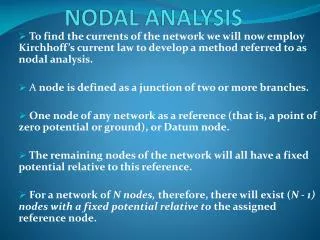
NODAL ANALYSIS
-. +. -. +. +. -. NODAL ANALYSIS.

NODAL ANALYSIS
E N D
Presentation Transcript
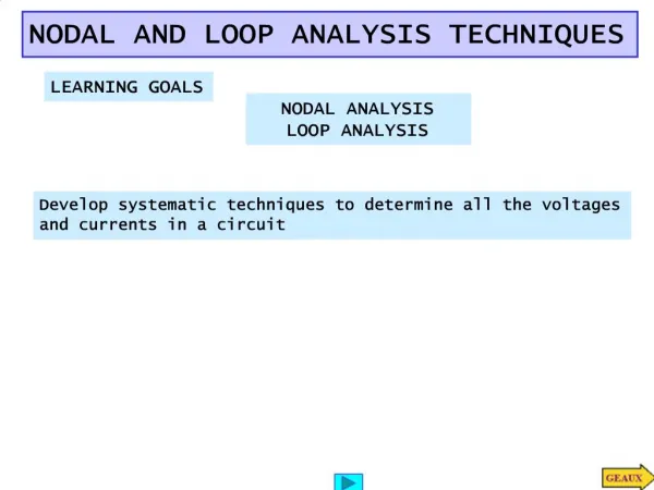
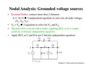
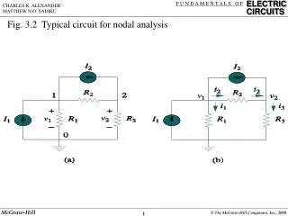
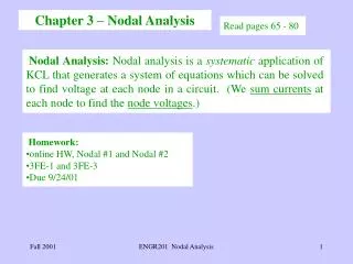
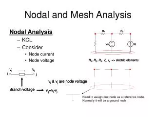
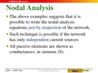
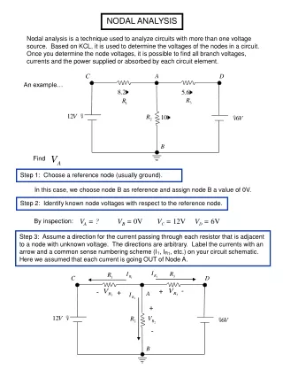
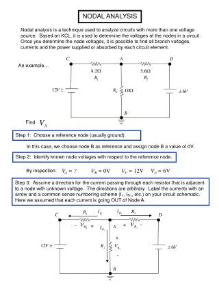
- + - + + - NODAL ANALYSIS Nodal analysis is a technique used to analyze circuits with more than one voltage source. Based on KCL, it is used to determine the voltages of the nodes in a circuit. Once you determine the node voltages, it is possible to find all branch voltages, currents and the power supplied or absorbed by each circuit element. An example… Find Step 1: Choose a reference node (usually ground). In this case, we choose node B as reference and assign node B a value of 0V. Step 2: Identify known node voltages with respect to the reference node. VA = ? VB = 0V VC = 12V VD = 6V By inspection: Step 3: Assume a direction for the current passing through each resistor that is adjacent to a node with unknown voltage. The directions are arbitrary. Label the currents with an arrow and a common sense numbering scheme (I1, IR1, etc.) on your circuit schematic. Here we assumed that each current is going OUT of Node A.
- + - + + - Step 4: Write KCL at the node with the unknown Voltage In this case VAis unknown, so write KCL for node A. Step 5: Express each branch current in terms of Ohm’s Law. Step 6: Express each element’s voltage as a difference between node voltages. To get the current, simply subtract the voltage at the tip of each current arrow from the voltage at the tail of the arrow, and then divide by the value of the associated resistor. Step 7: Substitute the known node voltages from Step 2.
Step 8: Substitute these equations back into the KCL equation from Step 3. Step 9: Plug in the resistor values. Drop the units here Step 10: Solve the equation for VA Now that you know the node voltage VA . . . . . . . . You know the voltage across each element . . . . You know the current through each element . . . . Power calculations are straightforward. If you have two or more unknown nodes, you will have more equations to solve. ** You must always have one equation for each unknown node. ** (2 unknown nodes 2 KCL equations)
Given: + - + - Step 2 Another example: Find VB, VC Step 1 Reference node is “D”
Step 4,5 Step 3 See drawing above for currents Step 6 2 unknown nodes (B, C) 2 KLC equations
Step 8 Step 7 Step 9 You should get These values are with respect to your Reference Node (D).