Simplifying Network Analysis Using Nodal Equations
150 likes | 247 Vues
Learn how to simplify network analysis through nodal equations. Convert practical voltage sources, write matrices, solve circuits, find currents, and determine node voltages effortlessly. Explore nodal and supernode approaches.

Simplifying Network Analysis Using Nodal Equations
E N D
Presentation Transcript
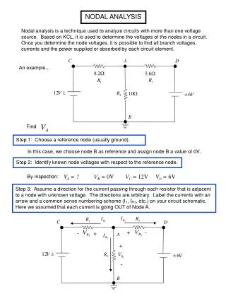
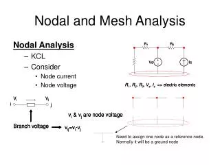
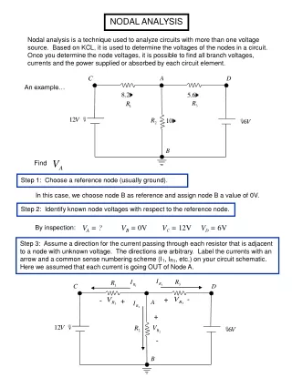
Next Nodal Analysis • The above examples suggests that it is possible to write the nodal analysis equations just byinspection of the network. • Such technique is possible if the network has only independent current sources. • All passive elements are shown as conductances, in siemens (S). Ch. 3 Network Analysis- Part II
Next • In case a network contains a practical voltage source, first convert it into an equivalent practical current source. • Write the Conductance Matrix, Node-Voltage Matrix and the Node-Current Source Matrix, in the same way as in the Mesh Analysis. Ch. 3 Network Analysis- Part II
Next Example 13 • Let us again tackle Example 12, by writing the matrix equations just by inspection. Ch. 3 Network Analysis- Part II
Next Conductance matrix. G11 = Self-conductance of node 1.G12= Mutual conductance between node 1 and 2. Ch. 3 Network Analysis- Part II
Next • Node-voltage Matrix. • Node current-source Matrix. • Note that all the elements on the major diagonal of matrix G are positive. • All off-diagonal elements are negative or zero. Ch. 3 Network Analysis- Part II
Next Example 14 • Solve the following network using the nodal analysis, and determine the current through the 2-S resistor. Ch. 3 Network Analysis- Part II
Next Solution : Ch. 3 Network Analysis- Part II
Next We can write the nodal voltage equation in matrix form, directly by inspection : Ch. 3 Network Analysis- Part II
Next Using Calculator, we get • Finally, the current through 2-S resistor is Ch. 3 Network Analysis- Part II
Next Example 15 • Find the node voltages in the circuit shown. Ch. 3 Network Analysis- Part II
Next Solution : First Method Transform the 13-V source and series 5-S resistor to an equivalent current source of 65 A and a parallel resistor of 5 S Ch. 3 Network Analysis- Part II
Next Now, we can write the nodal equations in matrix form for the two nodes just by inspection, Now, from the original circuit shown, we get Ch. 3 Network Analysis- Part II
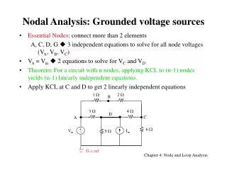
Click Next Second Method We use the concept of supernode. The voltage source is enclosed in a region by a dotted line, as shown in figure. The KCL is then applied to this closed surface: The KCL equation for node 1 is For three unknowns, we need another independent equation. This is obtained from the voltage drop across the voltage source, Writing the above equations in matrix form, Ch. 3 Network Analysis- Part II
Click Next Solving, we get Which are the same as obtained by first method. In general, for the supernode approach, the KCL equations must be augmented with KVL equations the number of which is equal to the number of the floating voltage sources. Ch. 3 Network Analysis- Part II
Next Choice Between the TWO • We select a method in which the number of equations to be solved is less. • The number of equations to be solved in mesh analysis is b – (n – 1) • The number of equations to be solved in nodal analysis is (n – 1) Ch. 3 Network Analysis- Part II