Download
1 / 39
390 likes | 563 Vues
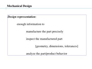
Mechanical Design. Design representation : enough information to manufacture the part precisely inspect the manufactured part [geometry, dimensions, tolerances] analyze the part/product behavior. Design models and data. Projections Theoretical technique to map 3D objects to 2D

E N D
Mechanical Design Design representation: enough information to manufacture the part precisely inspect the manufactured part [geometry, dimensions, tolerances] analyze the part/product behavior
Design models and data Projections Theoretical technique to map 3D objects to 2D Dimensions To assist machinist: e.g. distance between centers of holes Tolerances imprecision in machining must specify the tolerance range
Importance of tolerances What is a ‘good level of tolerance’? Designer: tight tolerance is better (less vibration, less wear, less noise) Machinist: large tolerances is better (easier to machine, faster to produce, easier to assemble) Tolerances interchangeability
Tolerance and Concurrent Engineering Why ? Tolerance specification needs knowledge of accuracy, repeatability of machines process capability …
Part 1. Projections 3D models: expensive, difficult to make Clay car model at GM need 2D representations Representation must convey feasible 3D objects
Geometric Projections: history Albrecht Durer’s machine [14??AD] (perspective map)
Importance of perspective maps 1. Renaissance architects Axonometric projection, Section view Duomo, Florence, Italy source and interesting history: http://www.mega.it/eng/egui/monu/bdd.htm 2. Modern CAD systems (a) 3D rendering, image processing (b) Mathematics of free-form surfaces (NURBS)
Why perspective maps ? Human sight and perception larger, farther same image size same size, farther smaller image
Perspective example parallel lines converge to a point The vanishing point (or station point)
Effect of vanishing point on perspective map Image on the ‘picture plane’ is a perspective of the 3D object [Is the object behind in perspective view ?]
Perspectives and vanishing points Perspectives in mechanical drafting Not good ! (1) parallel lines converge misinterpreted by the machinist (2) Views have too many lines
Orthographic views A mapping where parallel lines remain parallel How ? Set the vanishing point at infinity Another problem: Back, Sides of object not visible (hidden surfaces) Solution: Multiple views
Orthographic views.. Language of engineering communication
Orthographic views... View direction selection in orthographics Maximize true-size view of most faces
Different types of projections All engineering drawings must be made to scale
Part 2. ANSI dimensioning Datum: A theoretical geometric object (point, line, axis, or plane) derived from a specific part/feature of a datum feature on the part. Uses: (1) specify distance of a feature from the datum (2) specify a geometric characteristic (e.g. straightness) of a feature
ANSI dimensioning: definitions Feature: A geometric entity on the part, (hole, axis, plane, edge) Datum feature: An actual feature of a part, that is used to establish a datum. Basic Dimension: The theoretically exact size of a feature or datum
ANSI dimensioning: definitions.. Limits: The max/min allowable sizes Largest allowable size: upper limit Least allowable size: lower limit. LMC (Least Material Condition) MMC (Maximum material Condition)
Conventions for dimensioning (a) Specify tolerance for all dimensions (b) All necessary , sufficient dimensions X over-dimensioned X X under-dimensioned X Reference dimensions: Redundant dimensions, in ( …) (c) Dimensions should be (i) marked off the datum feature (ii) shown in true-size view (iii) shown in visible view
Part 3. Mechanical Tolerancing Conventional Tolerancing: (a) Size of a feature Specified by a basic size, and tolerance: 2.50±0.03 upper limit = lower limit = No of digits after decimal precision
Conventional Tolerancing.. Unilateral and Bilateral Tolerances:
Conventional Tolerancing... (b) The type of fit between mating features Designer needs to specify basic dia, tol of shaft: S±s/2 basic dia, tol of hole: H±h/2 Allowance: a = Dhmin – Dsmax
The hole-basic specification convention [Holes are made by drills]
Generalization of hole-basic/shaft-basic MMC: Maximum material condition LMC: Least material condition Hole at MMC at the lower limit Hole at LMC at the upper limit
Geometric Tolerancing Problems in Conventional tolerancing: (a) Assumes perfect surfaces (b) No use of Datums (c) No specification of form tolerances (d) X±t/2, Y±t/2 rectangular tolerance zone (cylindrical preferred)
Datums A theoretical feature (e.g. plane, line) Serves as a global coordinate frame for the part during different activities such as design, manufacturing and inspection. Each design must specify the datum planes (or other datums)
Datum feature The actual plane on the part (imperfect) corresponding to a (perfect) datum plane Sequence of establishing datums: PRIMARY (3 points) SECONDARY (2 points) TERTIARY (1 point)
Location tolerances Conventional system: rectangular tolerance zones True PositionTolerancing circular (cylindrical) tolerance zone
Concluding remarks - Design data must be shared Engineering drawings - Engineering drawings Importance of geometry - Tolerances Functional need, Manufacturing interchangeability - Tolerance specifications: Importance of Datums