Chapter 3 : Top Level View of Computer Functions
200 likes | 321 Vues
This chapter delves into the basic functions of a computer, focusing on how the CPU executes programs through the instruction cycle, which includes fetching and executing instructions stored in memory. It explains the roles of key components like the Program Counter (PC) and the Instruction Register (IR) in managing instruction flow. Additionally, the concept of interrupts is introduced, highlighting how various system components can signal the CPU to address important conditions or errors. The chapter provides a detailed overview of instruction formats, codes, and examples of program execution.

Chapter 3 : Top Level View of Computer Functions
E N D
Presentation Transcript
Chapter 3 : Top Level View of Computer Functions Basic CPU function, Interconnection, Instruction Format and Interrupt
3.2. The Computer Function • Basic function : program execution • Program : Set of instructions stored in memory • CPU fetches the instructions, one at a time and executes them one by one, according to the operation code • Simple way of thinking : two steps of instruction processing, fetch and execute • Actually, instruction execution may involve a number of steps • The processing time required for execution of a single instruction is called an instruction cycle time
3.2 Computer Function : Basic Instruction Cycle START Fetch Next Instruction Fetch Cycle Execute Instruction Execute Cycle HALT
3.2 Function - Fetch and Execute Cycles • An instruction is fetched to CPU using the address in PC (Program Counter) • Unless told otherwise, CPU always increment PC after fetching an instruction. PC points to next instruction. • Example : For instance PC is set to 300. After a fetch cycle, the PC is incremented by 1. PC points to location 301. This activity happens at PC unless CPU execute a jump instruction. • The fetched instruction is loaded into IR (Instruction Register) in the CPU. The instruction is in the form of binary code.
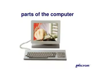
3. System Bus CPU Memory 3.1. Computer Components : ... 0 IR MAR Instruction 1 Instruction 2 MBR PC Instruction I/O AR ... I/O BR Data I/O Module Data Data n Buffers
3. System Bus CPU Memory 3.1. Computer Components : ... 0 IR MAR Instruction 1 Instruction 2 MBR PC Instruction I/O AR ... I/O BR Data I/O Module Data Data n Buffers
3. System Bus CPU Memory 3.1. Computer Components : ... 0 IR MAR Instruction 1 Instruction 2 MBR PC Instruction I/O AR ... I/O BR Data I/O Module Data Data n Buffers
3.2 Function - Instruction format & codes 0 3 4 15 OpCode Address • Consider a hypothetical machine : a. Instruction Format 0 1 15 Magnitude S b. Integer Format Program Counter (PC) = Address of Instruction Instruction Register (IR) = Instruction being Executed Accumulator (AC) = Temporary Storage c. Inter CPU Registers 0001 = Load AC from Memory 0010 = Store AC to Memory 0101 = Add to AC from Memory d. Partial List of Opcodes
3.2 Function -Example of program execution 0 3 4 15 Address (12 bits) OpCode Word length = 16 bit: 1. Assume PC contains 300. This content of location 300 is loaded into IR (First PC to MAR, READ, Memory xfer to MBR and finally MBR to IR). 2. The first 4 bit in IR indicate that AC is to to be loaded. The next 12 bits (940) specify operand address. 3. PC is incremented, next instruction is fetched 4. Old content of AC & content of location 940 are added, stored in AC. 5. PC is incremented, next instruction is fetched. 6. The content of AC are stored in location 941.
Instructions and Data in Memory • Instrcution (16 bits) Instruction & Data Memory (hexadecimal) Address ----------------------------------------------------------------------------------- 0001100101000000 1940 300 0101100101000001 5941 301 0010100101000001 2941 302 0000000000000011 0003 940 0000000000000010 0002 941 instructions data
3.2. Interrupt • Interrupt is a mechanism whereby a particular computer system component (I/O devices, Real Time Clock, Memory Unit, etc) could ask for CPU attention due to some very important condition occuring
Interrupt in Computer Systems Governed by : Operating Systems Interrupt : Mechanism to alert CPU, something needs its attention
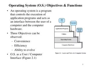
3.2 Interrupts Table 3.1 : Classes of Interrupts -------------------------------------------------------------------------- Program Generated by some condition that occurs as a result of an instruction execution, such as arithmetic overflow, division by zero, attempt to execute illegal instruction, reference outside user’s allowed memory space. Timer Generated by timer within the processor. This allows the O/Sto perform certain function on regular basis. I/O Generated by an I/O controller, to signal normal completion of an operation or to signal a variety of error conditions Hardware Failure Generated by failure, such as power or memory parity. -----------------------------------------------------------------------------------------
What happen with instruction cycle ? Instruction cycle with interrupt
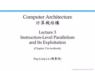
Example of Interrupt chain Printer Disk Floppy Keyboard 2 3 0 1 Interrupt register I0 Priority Encoder To CPU VAD I1 x Bus Buffers I2 y 0 I3 0 0 0 0 2 0 1 3 Mask register 0 Bus Buffer Enable line Signal line From CPU IST IEN Signal line tp CPU Mask Register could be set to 0, which disable the possibility of accepting interrupt signal from devices (0 through 3) IEN is a latch, that may be set by the CPU to enable/disable the acceptance of any interrupt form all devices
Example of Interrupt chain Printer Disk Floppy Keyboard 2 3 0 1 Interrupt register I0 Priority Encoder 1 1 1 VAD I1 0 1 1 Bus Buffers I2 0 1 1 0 I3 0 1 0 0 0 0 2 0 1 3 Mask register 0 IST IEN Interrupt to CPU Device 0 interrupt, mask-bit is 1. Interrupt signal reach Priority Encoder, going out with device code 11 (in VAD) Interrupt signal goes further to CPU, using the bottom side of the circuit (red lines)
Example of Interrupt chain Printer Disk Floppy Keyboard 2 3 0 1 Interrupt register Interrupt Address (VAD) (Vector) To CPU I0 Priority Encoder 1 1 1 VAD I1 0 1 1 Bus Buffers I2 0 1 1 0 I3 0 1 0 0 0 0 2 0 1 3 Mask register 0 Enable IE IST IEN INTACK from CPU Interrupt Acknowledged by the CPU (INTACK) Interrupt enable latch is set on (IEN) Interrupt signal, IEN signal and INTACKset theIEAND gate to pass interrupt enable signal to BUS Buffers Enabled by this signal, Bus Buffers send the interrupt address to CPU (the address of interrupt handler)