Download
1 / 42
540 likes | 933 Vues
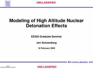
Modeling of High Altitude Nuclear Detonation Effects. EE350 Graduate Seminar Jon Schoenberg 18 February 2009. Outline. Background Motivation Effects Models Mitigation Summary. Space Weather Hazard: Radiation Belts. Radiation Belts (Schematic).

E N D
Modeling of High Altitude Nuclear Detonation Effects EE350 Graduate Seminar Jon Schoenberg 18 February 2009
Outline • Background • Motivation • Effects • Models • Mitigation • Summary
Space Weather Hazard: Radiation Belts Radiation Belts (Schematic) • Satellites are exposed continuously to Earth’s radiation belts • Radiation belts are highly dynamic • Frequent variations over several orders of magnitude • Strongly coupled to dynamics of global space environment • Radiation belts are recognized space hazard to satellites • Total Dose • Single Event Effects (SEE) • Surface and Internal DielectricCharging • Spacecraft are frequently upset and occasionally damaged beyond recovery • In practical terms, hardening is a limited solution; operational measures required CRRES Differential-Energy Measurements of Electron Flux Source: DTRA NWE Space Weather Brief Nov 05
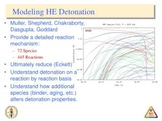
Scope of High Altitude Nuclear Effects • Systems that operate through the atmosphere, ionosphere, and space may be degraded by consequences of HAND via – • Fireball Electron Density (mean and variance) • Neutral Density (mean and variance) • Prompt and delayed radiation from debris • Plasma parameters (temperature, velocity) • Chemical composition (air species, debris) • Classes of Systems Impacted • RF system channels (communication, radar, navigation) • Optical Sensors • Electrical and Electronic systems (EMP, radiation, GIC effects) • Major Environmental Questions • How Severe? • How Widespread? • How Persistent? = scope of this seminar Source: HEART Conference Short Course Mar 98
Environment of High Altitude Nuclear Effects • Low air density above 100 km means: • Long mean free paths for X-rays and high velocity particles • Long ion-electron recombination times • Single 1 MT 200 km HAND can produce: • 106 kg of ionized air (roughly equivalent to whole ionosphere) • Persistent ionization lasting 10-20 hours • Intense trapped radiation belts (> 1 MeV betas) persisting for months-years • Neutral Heave – can increase density by 1,000x at 1,000 km • Destructive Electromagnetic Signals (Prompt-EMP, GIC) • -- prompt EMP can reach 104 V/m over wide areas • -- GIC (ground-induced currents) can destroy electrical distribution circuitry • Lofting and excitation of optically active species Source: HEART Conference Short Course Mar 98
Phenomenology of a High-Altitude Nuclear Detonation(above ~ 90 km altitude) S R T A ( S R U H D U H I O I V C V G A O N O ( X R T H F ~ R G I U I A R 7 N T R P D - H A G E I L R A Y % Y I A B I A S S ) N D 5 T R A N I H R G L O P G ; O O L L N E C ) M A K A S ; G M N A E C T I R C W E E E M A ( E W N N S T A A C E A E E U G P O B V R R D P N O L L E G G ( E L I A S N U I Z Y T S ( S I V D E L T I R C E D O F O W E I T B N A L W A R O U I L E V E R N A B E A E B I A L S B ; S A O T F S L E I L N V E O D L ; S E N N O R M P A A C T H C R R N H I E E O U I C C N O R M R C O - O N A A B M O I M M H D E D Z O O I I B B E R A A A I L I L M T T N N I T E I I I I N A A O C S O V G T T T U N E N I I ) R L O O ; Y E N N ; ; ; • Prompt Effects: Flash X-rays and Nuclear EMP • Trapped radiation belt formation and disturbed ionosphere driven by <25% of HAND yield • Complex physics transfers Debris KE (and its radiation/ionization) upward along Earth’s magnetic field and downward into ionized patch altering ionosphere • Ionospheric disturbance persist for hours • Trapped Radiation belts persist for months-years D E B R I S K I N E T I C B E T A S , N E U T R O N S , E N E R G Y G A M M A S ( ~ 1 % ) ( ~ 2 4 % ) M A G N E T I C C O N F I N E M E N T O F E X P A N D I N G W E A P O N D E B R I S SECONDS E R - A L F V E N I C ( S U B - A L F V E N I C D E B R I S E X P A N S I O N ) D E B R I S E X P A N S I O N ) b R E G I M E ) I N I T I A L P L A S M A S T R U C T U R E E S T A B L I S H E D ; W E A P O N D E B R I S C O N T A I N E D O R D I S P E R S E D ; 1 M T @ 2 0 0 K M Y I E L D S I O N I Z A T I O N E Q U A L T O W O R L D - W I D E I O N O S P H E R E ; E X C I T A T I O N O F E M I S S I V E S P E C I E S B Y X - R A Y P H O T O E L E C T R O N S ; b N U C L E A R T R A P P E D R A D I A T I O N B E L T F O R M E D B Y I N J E C T I O N M A G N E T O H Y D R O D Y N A M I C PLASMA R E C O M B I N A T I O N R I S E & E X P A N S I O N ; INSABILITIES A I R C MINUTES H E A V E ; B , E S T R U C T U R E G R O W T H ; E X P A N S I O N T O STRIATION G L O B A L S C A L E C O N V E C T I O N ; HOURS E L E C T R O S T A T I C D R I F T S T R U C T U R E Source: DTRA NEW NUDET Phenomenology Brief Nov 05 F R E E Z I N G H E A V E
Survey of Nuclear-Disturbed Regions1 MT at 400 km 1200 Log10 (Ne) (cm-3) Geomagnetic Field line 1 sec 30 sec 1000 Plasma rise andexpansion along geomagnetic flux tube 2 3 4 5 6 7 8 9 10 800 Air IonEnergy Patch Burst Point Burst Point 600 Altitude (km) 400 200 Gamma patch 0 Beta patch -200 - 700 Horiz. Range (km) + 700 - 700 Horiz. Range (km) + 700 Source: DTRA NWE Overview Brief Nov 05
Fireball / patch ionization formed between 100 - 200 km by air ions energized in collisionless super-Alfvenic blast wave Significant observations of systems effects during U.S. test: Destruction of satellites by long-lived trapped radiation; EMP on Hawaii Radio wave scintillation and absorption; radar clutter; widespread optical emissions Weapon debris to southern hemisphere; debris “jetting” to high altitudes Significant Questions and Uncertainties Relevant to Modern Systems: Debris dispersal; Trapped radiation;Energy coupling to air; Plasma striations STARFISH (U.S.) 1.4 MT at 400 km Soviet K3 Shot (?) (10/22/62) 300 kT at 290 km High-Alfven-Mach-Number Debris Expansion Regime (250 to 600 - 800 km) STARFISH Kinetic Energy Patch STARFISH Kinetic Energy Patch Time = 20 ms Time = 60 s Representative Tests Source: DTRA NEW NUDET Phenomenology Brief Nov 05
Outline • Background • Motivation • Effects • Models • Mitigation • Summary
One High Altitude Nuclear Detonation (HAND)Impacts Multiple Systems • High-altitude nuclear tests of 1958 and 1962 demonstrated wide-area effects with significant military impacts for numerous systems. • Radars: Blackout, absorption, noise, clutter, scintillation • Communications:Blackout, scintillation fading, noise, connectivity • Optical Sensors: IR, Visible, UV backgrounds, clutter; g noise • Satellites: Trapped radiation; radiation damage to electronics • Electronics & Power: Electromagnetic pulse; electrical systems damage ORANGE 3.8 MT at 43 km TEAK 3.8 MT at 76.8 km KINGFISH __ MT at __ km CHECKMATE __ MT at __ km STARFISH 1.4 MT at 400 km Source: Defense Threat Reduction Agency (DTRA)/Mission Research Corp briefing, 15 Jan 2003
Starfish Prime Objectives • Investigation of the basic characteristics of a HAND detonation and the physical basis of the effects • Evaluation of the effects of a HAND on electromagnetic surveillance capability • Evaluation of the effects of a HAND on long range communications • Evaluation of missile kill mechanisms produced by a High Altitude Nuclear Detonation (HAND) • Evaluation of HAND weapon diagnostic techniques • Evaluation of HAND detection systems
STARFISH RF Measurements 160o W 20o N Equator Rockets carried CW transmitters; observations made on JI and ships Late-time auroral measurements RF transmissions observed by ground, and airborne balloon locations
STARFISH UHF, HF, LF and VLF Comm 160o W 20o N Equator CONUS Far East More than 12 ground stations throughout Pacific Basin were involved
Example of STARFISH Reports in DTRIAC Guide to U.S. Atmospheric Nuclear Weapon Effects Data - DASIAC SR-92-007: Chapter 26: FISHBOWL Reports
Problem: Trapped Radiation Reduces LEO Satellite Lifetime A small LEO Nuke will disable virtually all LEO satellites in a few months LEO Satellites Alive Nuclear vs Natural Environment (~800km Polar Orbit) 1E+6 1E+5 1E+4 Dose (Rads Si) 1E+3 1E+2 Days into Campaign Nuclear 1E+1 Natural 1E+0 1 14 30 365 Days HAND Belt 50 kT, 31.3 deg, 75.2 deg, 200km 3 orders of magnitude more dose! Increased radiation causes LEO spacecraft to fail within months
Outline • Background • Motivation • Effects • Models • Mitigation • Summary
Radioactive weapon debris is lofted above atmosphere, then beta decays and emits high-energy electrons After beta particles are emitted, they are trapped by the Earth’s magnetic field and execute three types of motion (red arrows) Origins of Nuclear Burst Trapped Radiation Belts Weapon debris lofted above atmosphere. Beta particles are guided and trapped by Earth’s magnetic field Debris decays and emits beta particles (MeV electrons) Magnetic Field Lines Source: DTRA NWE NUDET Phenomenology Brief Nov 05
Nuclear Radiation Belts Schematic of Trapped Particle Motion • Combination of gyro, bounce, and drift motions creates a “drift shell” of trapped beta particles around the Earth • Ensemble of trapped beta particles creates a broad radiation belt (~ 0.1 Re) • Data from STARFISH nuclear test indicate nuclear trapped radiation belts persist for several months to years • Trapped radiation impinging on satellites can produce spacecraft charging • Trapped radiation can produce deep dielectric charging, single event upsets, and permanent damage to unhardened electronics Source: DTRA NWE NUDET Phenomenology Brief Nov 05
Starfish Nuclear Test RV Signal Amplitude Fading Waveform Distortion 10 0 Power (dB) Ground Based Radar -30 Time Time Delay High Altitude Nuclear Environment • Nuclear detonations produce intense ionospheric disturbances • Severe absorption and blackout • Widespread and long-lasting amplitude and phase scintillation • Angular scattering of signal • Disrupts communications and radar (signal fading and distortion)
Degraded RF Signals • Dynamic space environment includes ionospheric irregularities that induce signal scintillation that corrupts radio transmissions • HF CommunicationsUsable frequencies &operable links are uncertain during periods of ionospheric upset • GPS NavigationDegraded signals reducesystem accuracy; maydisable system for someusers • Satellite C4ISR LinksFading, increased errorrates, reduced bandwidth Source: DTRA NWE Space Weather Brief Nov 05
Starfish – Persistent Visual Effects Johnston Island 8 July 1962 [1.4 MT] [400 km] Minutes after Burst Red glow from 6300 Å (excited atomic oxygen) Yellow from fireball plume View from Christmas Island (south-east of burst) View from Northern aircraft Source: DTRA NWE Overview of Nuclear Test Data Brief Nov 05
Channel Parameters and Effects • Scintillation Parameters • Scintillation Index S4 • Measure of fading severity • Range: 0 (non-fading) to 1 (Worst Case Rayleigh fading) • Decorrelation Time 0 • Inverse measure of signal fading rate Range: sub msec to sec • Fast Fading Doppler spread and coherent processing degradation • Burst Errors in Slow Fading • Decorrelation Distances lx, ly • Measure of spatial decorrelation • Inverse measure of angular scattering • Antenna scattering loss, 0 , f0 filtering • Frequency Selective Bandwidth f0 • Inverse measure of delay spread • Range: kHz to carrier frequency • Inter-symbol interference and code correlator loss • Mean TEC Parameters • Total Electron Content (TEC) • Measure of enhanced electron density • 1 TEC unit = 1016 e/m2 • Range: 1018 e/m2 (peak natural) to >1020 e/m2 (nuclear) • Increased propagation delay and phase shift • Delay and Doppler shift dynamics from d(TEC)/dt • Absorption and Enhanced Sky Temperature • Loss of signal • Range: 0 dB to >100 dB • Increased noise temperature • Range: 100 degrees (natural) to >1000 (nuclear) Source: DTRA NWE PRPSIM Brief Nov 05
Scintillation and TEC Derived Fading is the scintillation index, I is the signal intensity, and Scintillation is the time average of the signal intensity TEC NT = Path-dependent Total Electron Content (TEC) in (el/m2), s is the propagation path and is the electron concentration (el/m3) Faraday Rotation is the Faraday rotation angle in radians, is the average Earth magnetic field in Teslas, is the TEC (el/m2), and f is the carrier frequency in GHz Group Delay delay time in seconds with reference to propagation in vacuum, f is the carrier frequency in Hz Signal Power Fluctuation Empirical Peak to Peak fluctuations in signal power Pflucin dB
Outline • Background • Motivation • Effects • Models • Mitigation • Summary
SCENARIO Family • High altitude (H > 120 km) atmospheric nuclear effects simulations • 10 kT to multi-MT yields, single burst or arbitrary multi-burst capability, extended simulation times (> 1 hour) • Environmental quantities for defense systems operability analyses: • SCENARIO — Plasma and heaved neutral atmosphere for radar and communication link applications • SMMARC — IR background scenes for optical sensor operability analyses • DGBETS — Delayed γ and β radiation environments for effects on sensors, spacecraft... • PRPSIM — RF channel parameters for propagation effects • Supported on Unix, Linux, and Windows PC's, or through API • DTRA’s ASSIST provides additional functionality for Windows users • Global SCENARIO is under development to replace SCENARIO, SMMARC, and GAMBET with much enhanced capability and improved physics models Source: DTRA NWE SCENARIO Brief Nov 05
Model Flow • For Radiation Belts • 1) Run SCENARIO for Nuclear Environment • Need to enable GAMBET capability • 2) Run DGBETS • Compute emission densities and 3-D b fluxes • 3) Run MAPIT:Plots flux maps • For Ionospheric Scintillation- and TEC-derived quantities • 1) Run SCENARIO for Nuclear Environment • 2) Run PRPSIM for propagation effects modeling • 3) Run PRPMAPIT:Plots propagation quantities
PRPSIM Propagation Effects Code • Nuclear Environments • SCENARIO Code • First Principles Phenomenology • Propagation Effects • DTRA Propagation Models • Scintillation • Absorption, Noise, TEC • Refraction • System Models • Satellite Orbits • Antennas • Terminals • Ballistic Missiles • Aircraft, etc. • Link Parameters • C/N0 • BER Models Source: DTRA NWE PRPSIM Brief Nov 05
PRPSIM Problem Specification • PRPSIM Is a Link Based Code: • Define Trajectories • Define Communications Hardware (Transmitter and Receiver Antennas and Modems) for Satellites and Terminals • Create Objects and Object Groups by Associating Transmitters and Receivers with Trajectories • Link Pairs of Objects or Groups at Specified Times • Obtain and Plot Channel and Performance Parameters for the Links at the Specified Times • Multiple Concatenated Links and Networks are Supported • (Up-/Cross-/Downlink, Uplink/Downlink Broadcast, etc.) • Contour Plots Are Obtained by Using Arrays of Links
Case 1: Sea of Japan 20 kT 300km HANDRadiation Belt Formation } LEO Slot GPS GEO Cross-section of Trapped Beta Belt 1 min post-detonation L=2 Burst Point • Peak of belt confined to ~0.1L around L=1.5 • Conjugate point reached within seconds of blast • Peak flux 104 greater than natural environment, persists for mos • Flux significantly greater than nature out to ~ L=3 altitude
Case 1: Sea of Japan 20 kT 300km HANDScintillation Contours • Persistent Scintillation at UHF throughout 24 hour period not seen at S-band or K-band
Case 2: Mid-CONUS 2 MT 250km HANDRadiation Belt Formation } LEO Slot GPS GEO • Peak of belt confined to ~0.2L around L=1.7 • Peak flux 106 greater than natural environment, persists for months • Slot region fills with significant beta flux for first month • Flux significantly greater than nature out to ~ L=4 altitude • Flux contributes in manner similar to severe solar storm from L=4 to L=7
Case 2: Mid-CONUS 2 MT 250km HANDFrequency-Dependent Scintillation Contours K-band S-band L-band • North and Westward drift due to circulation currents • Scintillation more severe and persistent at lower frequencies
Case 3: Mid-CONUS 2 MT 150km HANDFrequency-Dependent Scintillation Ground Contours S-Band GEO DL K-Band GEO DL
Case 3: Mid-CONUS 2 MT 150km HANDGPS Ground Tracks for DFW Reception NAV 60 NAV 46 NAV 27 NAV 62 NAV 47 NAV 57 NAV 44 NAV 48 NAV 26
Case 3: Mid-CONUS 2 MT 150km HANDTEC Contours and Effects on GPS Reception
Case 3: Mid-CONUS 2 MT 150km HANDCommunication Channels of Selected GPS SVs NAV 48 NAV 60 NAV 47 NAV 57
Outline • Background • Motivation • Effects • Models • Mitigation • Summary
Remediation with VLF Injected into Environment Radiative electron scattering caused by Navy VLF site “NWC” A small LEO Nuclear detonation may disable LEO constellations within a few months VLF Transmitters show promise as a means of precipating betas from orbit - Assumes assets hardened to just 2-times average (natural) radiation • Goals of Remediation would include • Reconstitution of environment in 1-2 months • This requires 2-3 years through natural processes without VLF transmitters • Save some LEO satellites (Tactical Impact if Responsively applied in 2-3 days) • Offset Solar Storms to increase spacecraft life (>10X of ambient)
Scintillation Mitigation Technology Steps in Scintillation Mitigation • Mitigation of fast phase scintillation • Modulation selection • Differential or noncoherent demodulation • Low rate encoding / decoding • Symbol repetition • Mitigation of slow amplitude fading • Error-correction encoding / decoding • Long interleaving / deinterleaving • Spatial diversity • Frequency diversity • Mitigation of frequency selective effects • Carrier frequency selection • Waveform selection • Robust tracking loop design • Adaptive equalization • Spatial / delay equalization • Error-correction encoding / decoding Mitigation techniques depend on system design and requirements
Outline • Background • Motivation • Effects • Models • Mitigation • Summary
Summary • High Altitude Nuclear Detonations produce numerous effects on systems--details depend on burst altitude and location • Persistently ionized, “structured” (striated) air plasma impacts RF systems via absorption, scintillation, and related effects • Radiation environments from weapon debris can degrade electronics functions or permanently damage components • Nuclear trapped radiation belts may impact satellite systems for months after the detonation • DTRA has developed a suite of codes that predict these environments • Scenario for Nuclear Environment • DGBETs for trapped radiation environment • PRPSim for RF propagation in highly scintillated environment