Download
1 / 15
160 likes | 321 Vues
Risk assessment for the thermosiphon cooling test system. D . Giugni Thermosiphon Review, Oct1 st 2009. General. When looking at the risk assessment for the thermosiphon , one should disentangle between the test and the full size plant .

E N D
Risk assessment for the thermosiphon cooling test system D. Giugni Thermosiphon Review, Oct1st 2009 Thermosiphon Review, Oct 1st 09
General When looking at the risk assessment for the thermosiphon, one should disentangle between the test and the full size plant. For the test setup, the FMEA (Failure Mode Effect Analysis) is rather simple and it indicates mild consequences for the system. The scope of the test is to demonstrate the functioning principle for C3F8 thermosiphon that has to deliver the fluid at a temperature and pressure suitable for the ID. All the strict requirements belonging to the safety of the detector and on the continuous run are not relevant here. Vice versa, the effects of the failures must be evaluated for the scaled up system since those might be showstoppers for the project. In the next slides the results of the analysis will be presented for both cases. Thermosiphon Review, Oct 1st 09
FMEA for the Test Setup Power cut None of the parts of the system is foreseen to be under UPS. In case of power cut, the chiller cooling power , the heater systems and the control system will be lost. Let assume that the plant is running at the time of the power cut with fluid circulating in both the by-pass line and the dummy load. The system evolves like this: • The normally “OFF” valves MEV2101 and MEV3101 shut off the feeding lines limiting the amount of liquid confined in non insulated pipes to about 10L • The heat pick-up boils off the fluid in the feeding lines and the lack of power in the heater systems will not allow to warm up the vapor to the room temperature. • The bottom part of the main exhaust line could reach a temperature below the caver dew point, condensing water or forming ice. • The pressure in the tank and in the exhaust lines will start to rise. The maximum expected pressure is driven by the saturation pressure and the maximum environmental temperature. Assuming and max air T @ 30C, the pressure in the exhausts and in the tank will reach ~10bara. Thermosiphon Review, Oct 1st 09
FMEA for the Test Setup (2) Chiller failure Chiller failure is similar to the power cut with exception that the heaters systems will be functional and it will prevent the condensation along the bottom of the exhaust lines. Heaters system failure In the by-pass . Need to close the inlet line to prevent the condensation on the exhaust. This does not necessary imply to turn off the plant since the flow required to keep it running can be handled by one of the two 1KW dummy load. The sequence: • The failure mode is detected by means of the T sensor TT 3101 • PLC turns off the MEV3101 • The operator might decide to divert the flow through the dummy loads and keep the plant running. In case no actions are taken (and the dummy load are off) the flow will stop. • The heat pick up in the feeding line might produce some boiling ad the top of the vertical feeding line. The effect can be detected by the pressure and temperature sensors at the top of the line and the operator can decide whether restarting the plant by warming it up or artificially rising the pressure in the tank injecting warm vapor. In the warm lines. Failure is detected by the TT2101. PLC turns off the valve MEV2101 to prevent ice formation. Thermosiphon Review, Oct 1st 09
FMEA for the test setup (3): Leaks Leaks Leaks will be detected by monitoring the tank level. Consequences depends upon the location of the leak : In the liquid lines A leak on the main vertical feeding line is the worst scenario. The leak can be detected by monitoring the liquid level and the PLC closes off the main inlet (MEV1101) and return (PV1101) valves . Nevertheless the localization of the leak might be extremely difficult and the repairing extremely time consuming. For this reason a leaks developed in the vertical feeding line is not considered as an “acceptable” failure mode. This pipe will be without flanges and all the welds 100% inspected with X rays. In the exhaust lines Depending upon the running conditions, the pressure in the exhaust lines are below 1 bara. A leak on those would cause air entering into the system rather than loosing of C3F8. Since air is lighter than the coolant, it will be collected in the top of tank. (see later for the purging procedure) Thermosiphon Review, Oct 1st 09
Risk assessment for the full scale plant The analysis of the failure effects is for the full scale plant more difficult. • P&I has not being worked out yet. The instrumentatons and devices listed there is the starting point for the FMEA. • The dynamic of the system (startup, shut down, transients, etc…) are the matter of the test plant and, at the moment, data and parameters are still unknown. Nevertheless it is worth to look at in this issue because we must evaluate whether scaling up the system to the full power and connecting it to the detector drive extras constraints from the risk assessment that must be considered during the design. Thermosiphon Review, Oct 1st 09
General considerations Several negative peculiarities of the actual plant that triggered many failure modes are solved by ‘design” : • C/PTFE contamination from piston rings. • Ni particulates from the cylinder coating. • H2O contamination from the cylinder. • Leaks induced by the vibration. … but troubles are moved to the chiller unit that becomes the critical part of the system. These are the failure modes and operation condition considered for the analysis • Power cut • Pressurization of the exhaust. • Failure of the detector heater systems • Contamination of the C3F8 • Failure in the main Hex in the condensation tank • Contamination of incondensable (Air) from leaks in the sub atmospheric section Thermosiphon Review, Oct 1st 09
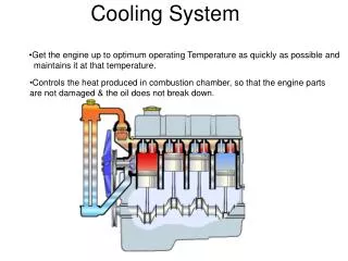
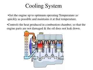
Power cut Unlikely the test setup, the main functionalities of the plant (control system, heaters, etc) will be under UPS. The compressors stage of the actual plant allows to deal with a limited power since can run with a single compressor over a total of 7. Vice versa the main chiller cannot run with reduced power and due the energy inefficiency of the thermosiphon (power is 180KW) it is unpractical to put the chiller under UPS. During the power cut, the system must be capable to deliver a cooling power for the actual “run degrade’ “ to keep the detector cold. The ex “run degrade” mode requires a cooling power of 8KW ,therefore assuming a factor 3 in the backup chillerpower ~25KW. This can be provided adding a secondary backup chiller under UPS that provides the required cooling power to the condenser. During a power cut, the PLC sets the plant to “ex run degrade’” mode activating the backup chiller and turning to STB all the loops except those for the thermal screen. Thermosiphon Review, Oct 1st 09
180KW 25 KW backup chiller pixel 6 X SCT BPR PR
Pressurization of the exhausts There are several cases in which the exhaust can be over-pressured above the detector MDP (4bara for Pixel). System STOP and main tank warms up When the plant is set to stop, the main inlet lines goes to OFF and the feeding lines from the racks are closed. The automatic valve on top of the main tank protects against the potential pressurization of the exhausts in case the tank warms up. Some of the liquid will be trapped in the detector loops but the recovery tank (installed in the actual plant to cope with the same problem) provides enough volume to keep the pressure below 4bara . Complete loss of cooling Power PLC turns all the loop to OFF, pressure in the tank rises up to ~10bara, but the fluid trapped in the loops expands in the discharge tank. Thermosiphon Review, Oct 1st 09
Pressurization of the exhausts (2) Double failure mode: main tank warm + valve PV1101 fails In this case the pressure in the exhaust lines follows the saturation pressure of the main tank. The discharge tank pressure also follows the one in the main tank until it reaches the limit and the C3F8 is dumped into the cooling room next to USA15. The detector MDP is fulfilled but: • Potential significant loss of the fluid. • Radiological issues for people working in USA15 in case of activation of the C3F8 Need to evaluate to: • install a purging line from the discharge tank to the surface to reduce the concentration of C3F8 in the cavern. • Install a redundant valve in series of the PV1101 (not 100% safe). Thermosiphon Review, Oct 1st 09
Failure in the main Hex in the condensation tank • A leak through the main HeX would drive to a contamination of the coolant (and vice versa). The P-T curve of the considered fluids (R134a) are lower than the one for the C3F8 and a contamination does not increase the pressure in the system. • However, the implication of such a failure are relevant and potentially dangerous for the chiller and for the plant. The piping entering the tank must be without flanges and with all the welds certified with 100% X-ray inspection. Thermosiphon Review, Oct 1st 09
Failure of the ID heaters system In case of loss of the heaters power, depending upon the load on the detector and upon the thermal pickup, the exhaust lines will start to be filled of liquid. The exhaust lines will freeze and the pressure rises accordingly to the height of fluid. • Pant should be set to STB (no flow through the detector and tank cold). Thermosiphon Review, Oct 1st 09
Contamination of incondensable (Air) • A leak in the sub-atmospheric section will drive to such air into the system. The top of the condensation tank is connected to collecting vessel where the air will be confined due to its lower density. • To purge the system, the collecting vessel is isolated from the tank and vacuum down. Thermosiphon Review, Oct 1st 09
Conclusions • The test system appears to be rather self safe. No particular indications on this. • The full size system is for the detector less “dangerous” then the actual compressors system: contamination risk is almost absence. A strict QA plan during the assembling is essential exclude leaks in crucial section of the piping. • Activated fluid release due to unforeseen pressurization of the exhaust is an issue to be better addressed. Thermosiphon Review, Oct 1st 09