Download

1 / 40
470 likes | 911 Vues
7. Transformations of Stress and Strain. Introduction Transformation of Plane Stress Principal Stresses Maximum Shearing Stress Example 7.01 Sample Problem 7.1 Mohr’s Circle for Plane Stress Example 7.02 Sample Problem 7.2 General State of Stress

E N D
7 Transformations of Stress and Strain
Introduction Transformation of Plane Stress Principal Stresses Maximum Shearing Stress Example 7.01 Sample Problem 7.1 Mohr’s Circle for Plane Stress Example 7.02 Sample Problem 7.2 General State of Stress Application of Mohr’s Circle to the Three- Dimensional Analysis of Stress Yield Criteria for Ductile Materials Under Plane Stress Fracture Criteria for Brittle Materials Under Plane Stress Stresses in Thin-Walled Pressure Vessels Transformations of Stress and Strain
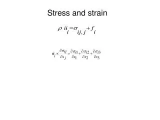
The most general state of stress at a point may be represented by 6 components, Introduction • Same state of stress is represented by a different set of components if axes are rotated. • The first part of the chapter is concerned with how the components of stress are transformed under a rotation of the coordinate axes. The second part of the chapter is devoted to a similar analysis of the transformation of the components of strain.
Plane Stress - state of stress in which two faces of the cubic element are free of stress. For the illustrated example, the state of stress is defined by • State of plane stress occurs in a thin plate subjected to forces acting in the midplane of the plate. • State of plane stress also occurs on the free surface of a structural element or machine component, i.e., at any point of the surface not subjected to an external force. Introduction
Consider the conditions for equilibrium of a prismatic element with faces perpendicular to the x, y, and x’ axes. • The equations may be rewritten to yield Transformation of Plane Stress
The previous equations are combined to yield parametric equations for a circle, • Principal stresses occur on the principal planes of stress with zero shearing stresses. Principal Stresses
Maximum shearing stress occurs for Maximum Shearing Stress
SOLUTION: • Find the element orientation for the principal stresses from • Determine the principal stresses from • Calculate the maximum shearing stress with Example 7.01 For the state of plane stress shown, determine (a) the principal panes, (b) the principal stresses, (c) the maximum shearing stress and the corresponding normal stress.
SOLUTION: • Find the element orientation for the principal stresses from • Determine the principal stresses from Example 7.01
Calculate the maximum shearing stress with • The corresponding normal stress is Example 7.01
Sample Problem 7.1 • SOLUTION: • Determine an equivalent force-couple system at the center of the transverse section passing through H. • Evaluate the normal and shearing stresses at H. • Determine the principal planes and calculate the principal stresses. A single horizontal force P of 150 lb magnitude is applied to end D of lever ABD. Determine (a) the normal and shearing stresses on an element at point H having sides parallel to the x and y axes, (b) the principal planes and principal stresses at the point H.
SOLUTION: • Determine an equivalent force-couple system at the center of the transverse section passing through H. • Evaluate the normal and shearing stresses at H. Sample Problem 7.1
Sample Problem 7.1 • Determine the principal planes and calculate the principal stresses.
With the physical significance of Mohr’s circle for plane stress established, it may be applied with simple geometric considerations. Critical values are estimated graphically or calculated. • For a known state of plane stressplot the points X and Y and construct the circle centered at C. • The principal stresses are obtained at A and B. The direction of rotation of Ox to Oa is the same as CX to CA. Mohr’s Circle for Plane Stress
With Mohr’s circle uniquely defined, the state of stress at other axes orientations may be depicted. • For the state of stress at an angle q with respect to the xy axes, construct a new diameter X’Y’ at an angle 2qwith respect to XY. Mohr’s Circle for Plane Stress • Normal and shear stresses are obtained from the coordinates X’Y’.
Mohr’s circle for centric axial loading: • Mohr’s circle for torsional loading: Mohr’s Circle for Plane Stress
SOLUTION: • Construction of Mohr’s circle Example 7.02 For the state of plane stress shown, (a) construct Mohr’s circle, determine (b) the principal planes, (c) the principal stresses, (d) the maximum shearing stress and the corresponding normal stress.
Principal planes and stresses Example 7.02
Example 7.02 • Maximum shear stress
SOLUTION: • Construct Mohr’s circle Sample Problem 7.2 For the state of stress shown, determine (a) the principal planes and the principal stresses, (b) the stress components exerted on the element obtained by rotating the given element counterclockwise through 30 degrees.
Sample Problem 7.2 • Principal planes and stresses
Stress components after rotation by 30o • Points X’ and Y’ on Mohr’s circle that correspond to stress components on the rotated element are obtained by rotating XY counterclockwise through Sample Problem 7.2
State of stress at Q defined by: • Consider tetrahedron with face perpendicular to the line QN with direction cosines: • The requirement leads to, • Form of equation guarantees that an element orientation can be found such that These are the principal axes and principal planes and the normal stresses are the principal stresses. General State of Stress • Consider the general 3D state of stress at a point and the transformation of stress from element rotation
Transformation of stress for an element rotated around a principal axis may be represented by Mohr’s circle. • The three circles represent the normal and shearing stresses for rotation around each principal axis. • Radius of the largest circle yields the maximum shearing stress. Application of Mohr’s Circle to the Three-Dimensional Analysis of Stress • Points A, B, and C represent the principal stresses on the principal planes (shearing stress is zero)
In the case of plane stress, the axis perpendicular to the plane of stress is a principal axis (shearing stress equal zero). • planes of maximum shearing stress are at 45o to the principal planes. Application of Mohr’s Circle to the Three-Dimensional Analysis of Stress • If the points A and B (representing the principal planes) are on opposite sides of the origin, then • the corresponding principal stresses are the maximum and minimum normal stresses for the element • the maximum shearing stress for the element is equal to the maximum “in-plane” shearing stress
If A and B are on the same side of the origin (i.e., have the same sign), then • planes of maximum shearing stress are at 45 degrees to the plane of stress Application of Mohr’s Circle to the Three-Dimensional Analysis of Stress • the circle defining smax, smin, and tmax for the element is not the circle corresponding to transformations within the plane of stress • maximum shearing stress for the element is equal to half of the maximum stress
Failure of a machine component subjected to uniaxial stress is directly predicted from an equivalent tensile test • Failure of a machine component subjected to plane stress cannot be directly predicted from the uniaxial state of stress in a tensile test specimen • It is convenient to determine the principal stresses and to base the failure criteria on the corresponding biaxial stress state Yield Criteria for Ductile Materials Under Plane Stress • Failure criteria are based on the mechanism of failure. Allows comparison of the failure conditions for a uniaxial stress test and biaxial component loading
Yield Criteria for Ductile Materials Under Plane Stress Maximum shearing stress criteria: Structural component is safe as long as the maximum shearing stress is less than the maximum shearing stress in a tensile test specimen at yield, i.e., For sa and sb with the same sign, For sa and sb with opposite signs,
Yield Criteria for Ductile Materials Under Plane Stress Maximum distortion energy criteria: Structural component is safe as long as the distortion energy per unit volume is less than that occurring in a tensile test specimen at yield.
Fracture Criteria for Brittle Materials Under Plane Stress Brittle materials fail suddenly through rupture or fracture in a tensile test. The failure condition is characterized by the ultimate strength sU. Maximum normal stress criteria: Structural component is safe as long as the maximum normal stress is less than the ultimate strength of a tensile test specimen.
Cylindrical vessel with principal stressess1 = hoop stresss2 = longitudinal stress • Hoop stress: • Longitudinal stress: Stresses in Thin-Walled Pressure Vessels
Points A and B correspond to hoop stress, s1, and longitudinal stress, s2 • Maximum in-plane shearing stress: • Maximum out-of-plane shearing stress corresponds to a 45o rotation of the plane stress element around a longitudinal axis Stresses in Thin-Walled Pressure Vessels
Spherical pressure vessel: • Mohr’s circle for in-plane transformations reduces to a point • Maximum out-of-plane shearing stress Stresses in Thin-Walled Pressure Vessels
Plane strain occurs in a plate subjected along its edges to a uniformly distributed load and restrained from expanding or contracting laterally by smooth, rigid and fixed supports Transformation of Plane Strain • Plane strain - deformations of the material take place in parallel planes and are the same in each of those planes. • Example: Consider a long bar subjected to uniformly distributed transverse loads. State of plane stress exists in any transverse section not located too close to the ends of the bar.
State of strain at the point Q results in different strain components with respect to the xy and x’y’ reference frames. • Applying the trigonometric relations used for the transformation of stress, Transformation of Plane Strain
Abscissa for the center C and radius R , • Principal axes of strain and principal strains, • Maximum in-plane shearing strain, Mohr’s Circle for Plane Strain • The equations for the transformation of plane strain are of the same form as the equations for the transformation of plane stress - Mohr’s circle techniques apply.
Rotation about the principal axes may be represented by Mohr’s circles. Three-Dimensional Analysis of Strain • Previously demonstrated that three principal axes exist such that the perpendicular element faces are free of shearing stresses. • By Hooke’s Law, it follows that the shearing strains are zero as well and that the principal planes of stress are also the principal planes of strain.
For the case of plane strain where the x and y axes are in the plane of strain, • the z axis is also a principal axis • the corresponding principal normal strain is represented by the point Z = 0 or the origin. • If the points A and B lie on the same side of the origin, the maximum shearing strain is out of the plane of strain and is represented by the points D’ and E’. Three-Dimensional Analysis of Strain • If the points A and B lie on opposite sides of the origin, the maximum shearing strain is the maximum in-plane shearing strain, D and E.
Consider the case of plane stress, • Corresponding normal strains, Three-Dimensional Analysis of Strain • Strain perpendicular to the plane of stress is not zero. • If B is located between A and C on the Mohr-circle diagram, the maximum shearing strain is equal to the diameter CA.
Strain gages indicate normal strain through changes in resistance. • With a 45o rosette, ex and ey are measured directly. gxy is obtained indirectly with, • Normal and shearing strains may be obtained from normal strains in any three directions, Measurements of Strain: Strain Rosette