The Data Link Layer
The Data Link Layer. Computer Network. Data Link Layer Design Issues. Node to Node Delivery Services Provided to the Network Layer Framing Error Control Flow Control. Functions of the Data Link Layer. Provide service interface to the network layer Dealing with transmission errors


The Data Link Layer
E N D
Presentation Transcript
The Data Link Layer Computer Network
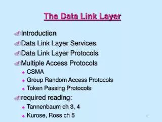
Data Link Layer Design Issues • Node to Node Delivery • Services Provided to the Network Layer • Framing • Error Control • Flow Control
Functions of the Data Link Layer • Provide service interface to the network layer • Dealing with transmission errors • Regulating data flow • Slow receivers not swamped by fast senders
Functions of the Data Link Layer Relationship between packets and frames.
Services Provided to Network Layer (a) Virtual communication. (b) Actual communication.
Framing A character stream. (a) Without errors. (b) With one error.
Framing (2) (a) A frame delimited by flag bytes. (b) Four examples of byte sequences before and after stuffing.
Framing (3) Bit stuffing (a) The original data. (b) The data as they appear on the line. (c) The data as they are stored in receiver’s memory after destuffing.
Error Detection and Correction • Error-Correcting • Error-Detecting
Error-Detecting Codes • Additional bits added by transmitter for error detection code • Parity • Value of parity bit is such that character has even (even parity) or odd (odd parity) number of ones • Even number of bit errors goes undetected
Error-Detecting CodesCRC – Cyclic Redundancy Check • Modulo 2 Arithmetic • Binary addition with no carries – Exclusive-OR
T=(k+n)- bit frame to be transmitted, with n<k • M=k-bit message, the first k bits of T • F=n-bit FCS, the last n bits of T • P=pattern of n+1 bits; this is the predetermined divisor
We would like T/P to have no remainder, thus; • T = 2nM + F By multiple m by 2n we have shifted it to the left by n bits and padded out the result with 0s. Adding F yields the concatenation of M and F which is T
how to get F • By dividing 2nM by P EQ-1 While R is the remainder
Thus, While R is the remainder
Prove: Divide T by P Substituting Equation with EQ-1
Error-Detecting Codes Calculation of the polynomial code checksum.
Flow Control (การจัดการ การไหลของข้อมุล) • ในการส่องข้อมูลระหว่าง 2 Nodes จำเป็นต้องมีการควบคุมการอัตราและจังหวะการส่องผ่านข้อมูลให้ relate กันทั้ง 2 Nodes
Elementary Flow Control Model For Frame Transmission
Stop and Wait • Source transmits frame • Destination receives frame and replies with acknowledgement • Source waits for ACK before sending next frame • Destination can stop flow by not send ACK • Works well for a few large frames
Fragmentation • Large block of data may be split into small frames • Limited buffer size (MTU– Maximum Transfer Unit) • Ethernet Data Payload MTU = 1500 Bytes • Errors detected sooner (when whole frame received) • On error, retransmission of smaller frames is needed • Prevents one station occupying medium for long periods • Stop and wait becomes inadequate
Sliding Window Protocols • A One-Bit Sliding Window Protocol • A Protocol Using Go Back N • A Protocol Using Selective Repeat
Sliding Windows Flow Control • Allow multiple frames to be in transit • Receiver has buffer W long • Transmitter can send up to W frames without ACK • Each frame is numbered • ACK includes number of next frame expected • Sequence number bounded by size of field (k) • Frames are numbered modulo 2k
Sliding Window Protocols (2) A sliding window of size 1, with a 3-bit sequence number. (a) Initially. (b) After the first frame has been sent. (c) After the first frame has been received. (d) After the first acknowledgement has been received.
Sliding Window Enhancements • Receiver can acknowledge frames without permitting further transmission (Receive Not Ready) • Must send a normal acknowledge to resume • If duplex, use piggybacking • If no data to send, use acknowledgement frame • If data but no acknowledgement to send, send last acknowledgement number again, or have ACK valid flag (TCP)
Flow & Error Control-- Stop and Wait or 1-Bit Sliding Windows • Source transmits single frame • Wait for ACK • If received frame damaged, discard it • Transmitter has timeout • If no ACK within timeout, retransmit • If ACK damaged,transmitter will not recognize it • Transmitter will retransmit • Receive gets two copies of frame • Use ACK0 and ACK1
Stop and Wait - Pros and Cons • Simple • Inefficient
Go Back N (1) • Based on sliding window • If no error, ACK as usual with next frame expected • Use window to control number of outstanding frames • If error, reply with rejection • Discard that frame and all future frames until error frame received correctly • Transmitter must go back and retransmit that frame and all subsequent frames
Go Back N - Damaged Frame • Receiver detects error in frame i • Receiver sends rejection-i • Transmitter gets rejection-i • Transmitter retransmits frame i and all subsequent
Go Back N - Lost Frame (1) • Frame i lost • Transmitter sends i+1 • Receiver gets frame i+1 out of sequence • Receiver send reject i • Transmitter goes back to frame i and retransmits
Go Back N - Lost Frame (2) • Frame i lost and no additional frame sent • Receiver gets nothing and returns neither acknowledgement nor rejection • Transmitter times out and sends acknowledgement frame with P bit set to 1 • Receiver interprets this as command which it acknowledges with the number of the next frame it expects (frame i ) • Transmitter then retransmits frame i
Go Back N - Damaged Acknowledgement • Receiver gets frame i and send acknowledgement (i+1) which is lost • Acknowledgements are cumulative, so next acknowledgement (i+n) may arrive before transmitter times out on frame i • If transmitter times out, it sends acknowledgement with P bit set as before • This can be repeated a number of times before a reset procedure is initiated
Go Back N - Damaged Rejection • As for lost frame (2)
Why Quota Win = 2^k -1 • Eliminate the confusion of go-back-n or move to the next frame sequence R T Frame 0 0 7 Frame 6 Frame 7 Go back N (Frame 0) Or Go to the Next Frame (Frame 0) Error at Frame 0 RR 0
Selective Reject • Also called selective retransmission • Only rejected frames are retransmitted • Subsequent frames are accepted by the receiver and buffered • Minimizes retransmission • Receiver must maintain large enough buffer • More complex login in transmitter
The Data Link Layer in the Internet A home personal computer acting as an internet host.
PPP – Point to Point Protocol The PPP full frame format for unnumbered mode operation.
PPP – Point to Point Protocol (2) A simplified phase diagram for bring a line up and down.