The Data Link Layer
Learn about framing techniques like bit stuffing to ensure accurate data reception. Error control methods include error-correcting codes and flow control mechanisms to manage data transmission rates effectively.

The Data Link Layer
E N D
Presentation Transcript
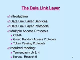
The Data Link Layer Chapter 3
Data Link Layer Design Issues • Services Provided to the Network Layer • Framing • Error Control • Flow Control
DLL Design FRAMING Bit Stuffing: IDEA: Use reserved bit patterns to indicate the start and end of a frame. For instance, use the 4-bit sequence of 0111 to delimit consecutive frames. A frame consists of everything between two delimiters. Problem: What happens if the reserved delimiter happens to appear in the frame itself? If we don't remove it from the data, the receiver will think that the incoming frame is actually two smaller frames! Solution: Use bit stuffing. Within the frame, replace every occurrence of two consecutive 1's with 110. E.g., append a zero bit after each pair of 1's in the data. This prevents 3 consecutive 1's from ever appearing in the frame. Chap. 3- DLL
DLL Design FRAMING • Bit Stuffing: • The receiver converts two consecutive 1's followed by a 0 into two 1's, but recognizes the 0111 sequence as the end of the frame. • Example: The frame "1 0 1 1 1 0 1" would be transmitted over the physical layer as "0 1 1 1 1 0 1 1 0 1 0 1 0 1 1 1". • Note: When using bit stuffing, locating the start/end of a frame is easy, even when frames are damaged. The receiver simply scans arriving data for the reserved patterns. • The receiver will re-synchronize quickly with the sender as to where frames begin and end, even when bits in the frame get garbled. • The main disadvantage with bit stuffing is the insertion of additional bits into the data stream, wasting bandwidth. How much expansion? The precise amount depends on the frequency in which the reserved patterns appear as user data. Chap. 3- DLL
Framing (3) Bit stuffing (a) The original data. (b) The data as they appear on the line. (c) The data as they are stored in receiver’s memory after destuffing.
DLL Design FRAMING Encoding Violations: Send a signal that doesn't conform to any legal bit representation. In Manchester encoding, for instance, 1-bits are represented by a high-low sequence, and 0-bits by low-high sequences. The start/end of a frame could be represented by the signal low-low or high-high. The advantage of encoding violations is that no extra bandwidth is required as in bit or character stuffing. The IEEE 802.4 standard uses this approach. Finally, some systems use a combination of these techniques. IEEE 802.3, for instance, has both a length field and special frame start and frame end patterns. Chap. 3- DLL
Error Detection and Correction • Error-Correcting Codes • Error-Detecting Codes
DLL Design ERROR CONTROL • Must insure that all frames are eventually delivered (possibly in order) to a destination. Three components are required to do this: • Acknowledgments, Timers, and Sequence Numbers • Acknowledgments: • Reliable delivery is achieved using the "acknowledgments with retransmission" paradigm. • The receiver returns a special acknowledgment (ACK) frame to the sender indicating the correct receipt of a frame. • In some systems, the receiver also returns a negative acknowledgment (NACK) for incorrectly-received frames. • This is only a hint to the sender so that it can retransmit a frame right away without waiting for a timer to expire. Chap. 3- DLL
DLL Design ERROR CONTROL • Timers: • One problem that simple ACK/NACK schemes fail to address is recovering from a frame that is lost, and as a result, fails to solicit an ACK or NACK. • What happens if an ACK or NACK becomes lost? • Retransmission timers are used to resend frames that don't produce an ACK. When sending a frame, schedule a timer to expire at some time after the ACK should have been returned. If the timer goes off, retransmit the frame. • Sequence Numbers: • Retransmissions introduce the possibility of duplicate frames. • To suppress duplicates, add sequence numbers to each frame, so that a receiver can distinguish between new frames and repeats of old frames. • Bits used for sequence numbers depend on the number of frames that can be outstanding at any one time. Chap. 3- DLL
DLL Design FLOW CONTROL Flow control deals with throttling the speed of the sender to match that of the receiver. Usually, this is a dynamic process, as the receiving speed depends on such changing factors as the load, and availability of buffer space. One solution is to have the receiver extend credits to the sender. For each credit, the sender may send one frame. Thus, the receiver controls the transmission rate by handing out credits. LINK INITIALIZATION: In some cases, the data link layer service must be "opened" before use: The data link layer uses open operations for allocating buffer space, control blocks, agreeing on the maximum message size, etc. Synchronize and initialize send and receive sequence numbers with its peer at the other end of the communications channel. Chap. 3- DLL
Error Detection & Control ERROR CORRECTING CODES In data communication, line noise is a fact of life (e.g., signal attenuation, natural phenomenon such as lightning, and the telephone worker). Moreover, noise usually occurs as bursts rather than independent, single bit errors. For example, a burst of lightning will affect a set of bits for a short time after the lightning strike. Detecting and correcting errors requires redundancy - sending additional information along with the data. There are two types of attacks against errors: Error Detecting Codes: Include enough redundancy bits to detect errors and use ACKs and retransmissions to recover from the errors. Error Correcting Codes: Include enough redundancy to detect and correct errors. We will introduce some concepts, and then consider both detection and correction. To understand errors, consider the following: Messages (frames) consist of m data (message) bits and r redundancy bits, yielding an n = ( m + r ) bit codeword Chap. 3- DLL
Error Detection & Control ERROR CORRECTING CODES Hamming Distance. Given any two codewords, we can determine how many of the bits differ. Simply exclusive or (XOR) the two words, and count the number of 1 bits in the result. This count is the Hamming Distance. Significance? If two codewords are d bits apart, d errors are required to convert one to the other. A code's Hamming Distance is defined as the minimum Hamming Distance between any two of its legal codewords (from all possible codewords). In general, all 2m possible data words are legal. However, by choosing check bits carefully, the resulting codewords will have a large Hamming Distance. The larger the Hamming distance, the better the codes are able to detect errors. To detect d 1-bit errors requires having a Hamming Distance of at least d + 1 bits. Why? To correct d errors requires 2d + 1 bits. Intuitively, after d errors, the garbled messages is still closer to the original message than any other legal codeword. Chap. 3- DLL
Error Detection & Control ERROR CORRECTING CODES Parity Bits A single parity bit is appended to each data block (e.g. each character in ASCII systems) so that the number of 1 bits always adds up to an even (odd) number. 1000000(1) 1111101(0) The Hamming Distance for parity is 2, and it cannot correct even single-bit errors (but can detect single-bit errors). As another example, consider a 10-bit code used to represent 4 possible values: "00000 00000", "00000 11111", "11111 00000", and "11111 11111". Its Hamming distance is 5, and we can correct 2 single-bit errors: For instance, "10111 00010" becomes "11111 00000" by changing only two bits. However, if the sender transmits "11111 00000" and the receiver sees "00011 00000", the receiver will not correct the error properly. Finally, in this example we are guaranteed to catch all 2-bit errors, but we might do better: if "00111 00111" contains 4 single-bit errors, we will reconstruct the block correctly. Chap. 3- DLL
Error Detection & Control ERROR CORRECTION What's the fewest number of bits needed to correct single bit errors? Let us design a code containing n = m + r bits that corrects all single-bit errors (remember m is the number of message (data) bits and r is number of redundant (check) bits): There are 2m legal messages (e.g., legal bit patterns). Each of the m messages has n illegal codewords a distance of 1 from it. That is, if we systematically invert each bit in the corresponding n-bit codeword, we get illegal codewords a distance of 1 from the original. Thus, each message requires n + 1 bits dedicated to it (n that are one bit away and 1 that is the message). The total number of bit patterns is ( n + 1 ) * 2m< 2n. That is, all (n+1) * 2m encoded messages should be unique, and there can't be fewer messages than the 2n possible code-words. Since n = m + r , we get: ( m + r + 1) * 2m< 2m+r or ( m + r + 1) < 2r This formula gives the absolute lower limit on the number of bits required to detect (and correct!) 1-bit errors. Chap. 3- DLL
Error-Correcting Codes Use of a Hamming code to correct burst errors.
Error Detection & Control ERROR DETECTION Error correction is relatively expensive (computationally and in bandwidth.) For example, 10 redundancy bits are required to correct 1 single-bit error in a 1000-bit message. In contrast, detecting a single bit error requires only a single-bit, no matter how large the message. The most popular error detection codes are based on polynomial codes or cyclic redundancy codes(CRCs). Allows us to acknowledge correctly received frames and to discard incorrect ones. Tanenbaum and you have worked several examples. Chap. 3- DLL
Error-Detecting Codes Calculation of the polynomial code checksum.