The Data Link Layer
Understand link layer services, error detection, correction, multiple access protocols, LAN technologies (Ethernet, IEEE 802.11), addressing, and more. Includes concepts like link capacity, latency, throughput, and bandwidth-delay product. Explore modulation, encoding, and data framing.

The Data Link Layer
E N D
Presentation Transcript
The Data Link Layer Based on slides by Shiv. Kalyanaraman and B. Sidkar RPI Kurose and Ross from their book Modified by Michalis Faloutsos UCR
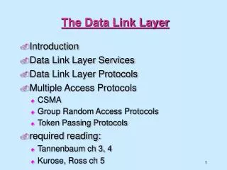
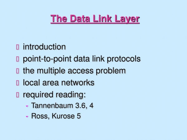
Overview • link layer services • error detection, correction • multiple access protocols and LANs • link layer addressing, ARP • specific link layer technologies: • Ethernet • IEEE 802.11 LANs • PPP • ATM • hubs, bridges, switches
network link physical M H H H H H H H H H l t n n t l t n t M data link protocol M application transport network link physical M frame phys. link Link Layer: setting the context - 2 • two physically connected devices: • host-router, router-router, host-host • unit of data: frame M adapter card
Link Layer Services - 1 • Framing, link access: • encapsulate datagram into frame, adding header, trailer • implement channel access if shared medium, • ‘physical addresses’ used in frame headers to identify source, dest • different from IP address!
Link Layer Services - 2 • Reliable delivery between two physically connected devices: • seldom used on low bit error link (fiber, some twisted pair) • wireless links: high error rates • Q: why both link-level and end-end reliability?
Link Layer Services - 3 • Flow Control: • pacing between sender and receivers • Error Detection: • errors caused by signal attenuation, noise. • receiver detects presence of errors: • signals sender for retransmission or drops frame • Error Correction: • receiver identifies and corrects bit error(s) without resorting to retransmission
M H H H H H H H H H network link physical t t l n n l t n t M M application transport network link physical data link protocol M M frame phys. link adapter card Link Layer: Implementation • Implemented in “adapter” • e.g., PCMCIA card, Ethernet card • typically includes: RAM, DSP chips, host bus interface, and link interface
Some basic concepts • Link capacity limits • Bandwidth and throughput • Bandwidth delay product • Note: many times the definition depends on the context
Link Capacity: Shannon • How much capacity (data rate) can a link support? • Shannon’s theorem - classic theorem: • C = B log2 (1 + S/N) • Where • C is link capacity • B is the bandwidth of the line • S is average signal power • N is average noise power • S/N is the signal to noise ratio • Expressed in decibels: db = 10 log10 (S/N) • Signal strength is reported relative to noise • Assume db = 30, and B = 3000Hz (phone line) • Then log10 (S/N) = 3 => S/N = 1000 • From Shannon’s: C = 3000 log2(1+1000) ~ 30Kbps
Bandwidth • See PetDav p.40 • Bandwidth: the range of frequencies a channel can use • Tel. Line: 300 - 3300Hz -> 3000Hz • How fast we can push bits out • Bandwidth commonly used as number of bits per sec that can be transmitted
Latency • How long does a packet take to go from one host to another. • Also called “Delay”. Latency = Node processing + Queueing Delay + Transmission Delay + Propagation Delay Depending on context delay can refer to subset of the above delays Link delay = Transmission + Propagation
Throughput • Throughput: the number of bits that can be delivered successfully defined per layer • For Link level, same as bandwidth • For application level, information that can go through • Goodput: useful throughput • throughput - overhead
Round Trip Time • Packet is sent from sender to receiver. • Receiver sends ACK (assume immediately) to sender. • Total time delay incurred between the instance the packet is set to the time the ACK is received. • Note: if forward delay = backward delay, RTT = 2 * Delay (although not always accurate).
Bandwidth Delay Product • B, Bandwidth is how fast I can push bits on the link • D, Delay is the time it takes for information to arrive at the destination • B x D is the amount of bits that can be in flight on a link before the receiver is aware of anything Delay Bandwidth
Example • For a transcontinental channel -- latency = 50 milliseconds. • Bandwidth = 45 Mbps. • Bandwidth delay product = 50 x 10-3 x 45 x 106 = 2.25 Mbits • We can transmit 2.25 M bits before the first bit reaches the other end of the channel !
What if ACK is expected ? • Note if ACK is expected, how many bits can the user transmit before he expects to have an ACK ? • RTT X Bandwidth • For symmetric channels, we can assume: RTT = 2 X Delay X Bandwidth.
Modulation • Data is in bits -- we need to somehow translate this to signal variations. • This process is modulation. • Vary either the amplitude, frequency or phase of the signal --- dictated by the bit stream.
Encoding • Represent binary data as signals. • Let us ignore modulation for the moment. • We have two signals -- high and low for representing 0s and 1s. • signals represent voltages. • 1 is high voltage, 0 is low voltage • As an example +5 V and -5 V.
The NRZ scheme • Straighforward: • High voltage = 1 • Low voltage = 0
Problems with NRZ • Receiver keeps an average of the signal received so far. • Compares incoming signal to this average • If significantly higher -- high, if significantly lower, then low. • If too many zeroes or ones, difficult to track this average -- the average wanders -- called the baseline wander. • If there are clock drifts between the sender and receiver, this cannot be detected -- how many bits were transmitted ?
Other encoding schemes • NRZI : Transition from current signal to encode a `1’. Stay at the same signal if it is a `0’. • Solves problem with consecutive 1s but not zeroes.
Manchester Encoding • X-OR the NRZ with a clock • 0 --> represented as a low to high transition. • 1 -- > represented as a high to low transition.
Problems with Manchester Encoding • Doubles the rate of transitions. • Half the time for the receiver to detect each pulse • Increase in complexity • Bit rate = 1/2 Baud rate for Manchester encoding. • baud rate represents signal rate a channel property • Bit rate : how many bits (information) I can send • Typically: • Bit rate is lower than baud rate • In some cases, • bit rate could be higher than baud rate -- multiple bits mapped onto a signal. • See PetDavie
Error Detection - 1 • EDC= Error Detection and Correction bits (redundancy) • D = Data protected by error checking, may include header fields • Error detection check if there is an error • protocol may miss some errors, but rarely • larger EDC field yields better detection and correction • Error detection code introduce overhead • More bits to send!
Parity Checking Single Bit Parity: Detect single bit errors Two Dimensional Bit Parity: Detect and correct single bit errors 0 0
Sender: treat segment contents as sequence of 16-bit integers checksum: addition (1’s complement sum) of segment contents sender puts checksum value into checksum field Receiver: compute checksum of received segment check if computed checksum equals checksum field value: NO - error detected YES - no error detected. But maybe errors nonetheless? Internet checksum Goal: detect “errors” (e.g., flipped bits) in transmitted segment (note: used at transport layer only)
Multiple Access Links and Protocols Three types of “links”: • Point-to-point (single wire, e.g. PPP, SLIP) • Broadcast (shared wire or medium; e.g, Ethernet, Wavelan, etc.) • Switched (e.g., switched Ethernet, ATM etc)
Multiple Access Protocols - 1 • single shared communication channel • two or more simultaneous transmissions by nodes: interference • only one node can send successfully at a time • multiple access protocol: • distributed algorithm that determines how stations share channel, i.e., determine when a station can transmit
Multiple Access Protocols - 2 • multiple access protocol (cont.): • communication about channel sharing must use channel itself! • Issues in multiple access protocols: • synchronous or asynchronous • information needed about other stations • robustness (e.g., to channel errors) • performance
Multiple Access protocols - 3 • claim: humans use multiple access protocols all the time • How do we share?
MAC Protocols: a taxonomy Three broad classes: A. Channel Partitioning Protocols • divide channel into smaller “pieces” (time slots, frequency) • allocate piece to node for exclusive use B. Random Access Protocols • allow collisions • “recover” from collisions C. “Taking turns” Protocols • tightly coordinate shared access to avoid collisions Goal:efficient, fair, simple, decentralized
Channel PartitioningMAC protocols: TDMA - 1 TDMA: time division multiple access • Access to channel in "rounds" • Each station gets fixed length slot (length = pkt trans time) in each round • Unused slots go idle • Example: 6-station LAN, 1,3,4 have pkt, slots 2,5,6 idle
time frequency bands Channel Partitioning MAC protocols: FDMA - 2 • Example: 6-station LAN, 1,3,4 have pkt, frequency bands 2,5,6 idle
Channel Partitioning (CDMA) - 1 CDMA (Code Division Multiple Access) • used mostly in wireless broadcast channels (cellular, satellite, etc) • all users share same frequency, • but each user has own “chipping” sequence (ie code) to encode data • Users can transmit at the same time!
Channel Partitioning (CDMA) - 2 • Encoded signal = (original data) X (chipping sequence) • Decoding: (received data) X (chipping sequence) • Think of it as multiplying with 1 or -1 twice Not in Peterson Davie!
Performance of channel partitioning • Dividing resources (e.g in time) • Avoids collisions • May lead to inefficient use of the channel • A channel not used by “owner” stays idle • Assume: N users: Channel capacity C / N per user • Only one user active: 1/N utilization
Performance of Fixed Assignment Protocols - 1 • Fixed assignment protocols are ideal for continuous streams such as video or audio • What about for packet switched data? • A “perfect” multiple access scheme would always use the channel when there are packets waiting (statistical multiplexing) • The mean delay for statistical multiplexing is just like for the M / M / 1 queue: where is the arrival rate and is the service rate
Performance of Fixed Assignment Protocols - 2 • Fixed assignment protocols divide the channel into N separate independent, /N identical subchannels • If each user has arrival rate /N, each user/subchannel pair can be modeled as a separate M / M / 1 queue • And the mean delay for a packet is • So, if we use fixed assignment protocols for packet switched data, mean delay goes up by a factor of N!!
Random Access Protocols - 1 • When node has packet to send • transmit at full channel data rate R. • no a priori coordination among nodes • Two or more transmitting nodes -> “collision”, • Random access MAC protocol specifies: • how to detect collisions • how to recover from collisions (e.g., via delayed retransmissions)
Random Access Protocols - 2 • Examples of random access MAC protocols: • ALOHA (not in PetDavie) • slotted ALOHA (not in PetDavie) • CSMA and CSMA/CD
The Rules of Sharing • CSMA: Collision Sensing Multiple Access • Sense the channel before sending • CSMA/CD: CSMA with Collision Detection • Sense the channel before sending • Sense the channel WHILE sending too
Pure (unslotted) ALOHA - 1 • Unslotted Aloha: simpler, no synchronization • pkt needs transmission: • send when you have a packet (expect ack) • If failure, wait some time and retry • Collision: pkt sent at t0 collide with pkts sent in [t0-1, t0+1]
Carrier Sensing Multiple Access (CSMA) - 1 • In some shorter distance networks, it is possible to listen to the channel before transmitting • In radio networks, this is called “ sensing the carrier” • Human analogy: Don’t interrupt others • The CSMA protocol works just like Aloha except: If the channel is sensed busy, then the user waits to transmit its packet, and a collision is avoided • This really improves the performance in short distance networks!