Download
1 / 27
270 likes | 410 Vues
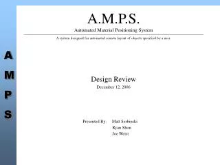
A.M.P.S. Automated Material Positioning System. A system designed for automated remote layout of objects specified by a user. Design Review December 12, 2006 Presented By: Matt Serbinski Ryan Shon Joe Weist. Agenda. Overview of System

E N D
A.M.P.S.Automated Material Positioning System A system designed for automated remote layout of objects specified by a user. Design Review December 12, 2006 Presented By: Matt Serbinski Ryan Shon Joe Weist
Agenda • Overview of System • Review of Major Component Design • Movement Grid • Placement Robot • Base Station • Discussion
Movement Grid Columns Robot Rows Block Storage Tower Base Station Overview • 3 Major Components • Movement Grid – Area of “authorized movement” for robot. Also stores blocks for layout. • Placement Robot – Robot responsible for physical replication of input block layout • Base Station – Human-Machine Interface for a user to command/monitor the remote robot.
Movement Grid • 6 Rows x 6 Columns • Border is considered out of bounds for blocks • Only grid intersections are valid locations for block placement • Masonite base • Lines made of reflective tape
Block / Block Storage • Provides storage of 10 blocks for robot to layout • Made of wood • Elevated so robot does not have to “pick up” blocks • Blocks are 2-inch square and are made of rigid foam
Placement Robot • 6 Major Subsystems • Locomotion • Navigation • Communication • Power • Control • Gripper
Casters Opto-Reflector Sensors 68HC12 Controller Motor Control / Wireless / Power Circuitry Robot – 2
Linear Actuator Gripper • Made of Erector set components • Originally powered by RC servo with threaded rod adjustment. • Required feedback control to grip block
Gripper – 2 • New design uses miniature linear actuator • No external feedback necessary (has a built-in encoder) • Provides Simple Control
0,0 : 0 0,1 : 1 0,2 : 2 0,3 : 3 0,4 : 4 1,0 : 5 1,1 : 6 1,2 : 7 1,3 : 8 1,4 : 9 2,0 : 10 2,1 : 11 2,2 : 12 2,3 : 13 2,4 : 14 3,0 : 15 3,1 : 16 3,2 : 17 3,3 : 18 3,4 : 19 4,0 : 20 4,1 : 21 4,2 : 22 4,3 : 23 4,4 : 24 Block Storage Tower Back End Message Format Parameter Format* * $20 will be added to the parameter to ensure printable ASCII characters
Back End: Block Placement Algorithm 1. Procedure begins with robot at block supply tower with the gripper open. 2. Close the grippers on the block. 3. Back robot away from block tower to first row. 4. Turn robot 90 degrees so that it is pointed along the row line according to placement priority. 5. Move robot along row line to the appropriate column. 6. At the column, turn robot toward the far end of the board, to follow the column line. 7. Move robot along the column line to the appropriate row and stop so that the block will be over the intersection where it is to be dropped. 8. Open gripper, dropping block at desired intersection. 9. Back robot away from placed block. 10. Turn robot 180 degrees. 11. Move robot along column line back to the first row. 12. Turn robot 90 degrees to follow the row line. 13. Move robot to follow row line to column along which the block tower is located. 14. Turn robot 90 degrees to face block tower. 15. Move robot forward to block tower. 16. Go to step 1 if there are more blocks to be placed.
Communication Hardware • Aircable USB • Creates a virtual serial port • Aircable Serial OS • Inherits the settings of the virtual COM port • Rechargeable Lithium Poly Battery • Intelligent Bluetooth microcontroller • Cable Mode • Only paired Aircable products can communicate (information is stored in flash memory) • 30 – 50 foot range • 1200 – 231400 bps baud rate, 8 data bits, none, even or odd parity, one or two stop bits • 160 kb/sec data transfer
Testing Physical, positional and velocity specification compliance as well as major subsystem compliance will be performed at this stage as follows: • Robot will be weighed and dimensions measured for compliance. • Using measured straight lengths the straight-line speed will be tested. • At an intersection, the robot will be made to continuously turn to test turning radius. • At an intersection, the robot will be instructed to move forward by the smallest increment possible to test adjustment resolution. • The robot will be instructed to traverse an entire row then column to test positional accuracy. The positional accuracy of the robot will be measured at each intersection. • At the block storage tower, the time taken to grasp the block will be measured to test grasp speed. • The block mass will be measured to ensure specification compliance. • A full layout will be input and the blocks placed to determine the error rate as well block placement accuracy. • The completed robot will be probed to test maximum current draw while being instructed to run continuously to test battery life.
Testing Once the robot has been successfully integrated into the system the base station testing will proceed as follows: • The base station will be timed while being started and stopped to test start up and shutdown timing compliance. • The completed robot will be fed a (possibly invalid) layout involving the maximum number of instructions to test instruction storage. • The distance between the movement grid and base station will be increased until reliable communication is no longer possible. • Layouts of various sizes will be setup and fed to the robot to test proper layout size boundaries. • The base station control software will be monitored during the layout process to test the status update rate. Upon successful integration of the base station into the system, several formal verification runs will be conducted to ensure proper system functionality.
Discussion • Questions/Comments