Download
1 / 20
210 likes | 1.14k Vues
Study of Contact Resistance in Ohmic Contacts for GaN devices. By Uttam Reddy ECE 445.

E N D
Study of Contact Resistance in Ohmic Contacts for GaN devices By Uttam Reddy ECE 445
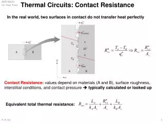
Objective: To compare the contact resistance in Ohmic Contacts for GaN devices in two inherently different Transmission Line (TLM) patterns.Contact Resistance:Resistance at the metal-semiconductor interfaceImportance of Lowering Contact Resistance • Increases drain current • Lowers pinch-off voltage • Lowers power consumption • Increases breakdown voltage
Advantages ofusing GaN Optical Applications • Wide Band Gap (3.4 eV) • Direct Band Gap Power Electronic Applications • Good Ohmic contact • High Breakdown Voltage • Chemically stable • Large Current Carrying Ability
Design Overview Two different Transmission Line Patterns were fabricated Pattern I Metal Deposited on n-GaN layer Pattern II n+ GaN layer inserted between Metal and n-GaN layer TLM
Fabrication of Pattern I n-GaN layer (Epi) grown on GaN Template using Plasma Assisted Molecular Beam Epitaxy (PAMBE) n-GaN doping : 2E17/cm3 of Si Pressure: 10-6 Torr Temperatures: Ga: 1000 C Si: 1200 C n-GaN Layer Professor Kim’s MBE Machine GaN Template
Atomic Force Microscopy Important to look for Pinholes after growth, Too many Pinholes increase Contact Resistance
After Lift- Off Expose to UV light through the mask Apply Photo-Resist Metal Evaporation after Developing After Developing
~300 A Au ~300 A Ti Al ~900 A ~300 A Ti Metal Contacts • Gold: Noble Metal • Aluminum: Ohmic Metal • Titanium: • Prevents gold from diffusing • Upon Annealing forms TiN
Annealing Done at 850C for 30 seconds. Advantages: • Tunneling • Helps in the formation of TiN
Pattern I 5 um 10 um 20 um 40 um Ti/Al/Ti/Au Z 0.2um MBE grown n-GaN MOCVD grown n-GaN
Fabrication of Pattern II Grow n-GaN layer on GaN template Grow n+ GaN layer on n-GaN layer (5E18/cm3 of Si) Deposit Silicon Dioxide Silicon Dioxide is etched n+ GaN layer is dry etched with chlorine gas After removal of Silicon Dioxide
Expose to UV light through the mask Apply Photo-Resist Metal Evaporation after Developing After Developing After Lift- Off and Annealing
Pattern II n+ GaN Layer 5 um 10 um 20 um 40 um Ti/Al/Ti/Au Z ~ 0.2 um MBE Grown n-GaN MOCVD Grown n-GaN
V 5 um 10 um 20 um 40 um Testing and Theory • I-V curve plotted at a distance of 5um • Voltage swept from 1V to -1V • I-V curves also plotted at 10um, 20um and 40um • Total Resistance calculated from the obtained I-V curves • Total Resistance is then plotted against distance to get a linear curve
Total Resistance Slope = Rsheet/Z 2*Rc 5 um 10 um 20 um 40 um d (um) 2*LT Rsheet = (Rc * Z) / LT Z = 200um LT = ( X / Rsheet)0.5 X is the specific contact Resistivity LT is the distance below the metal contact where the applied voltage gets attenuated by 1/e
I-V Curves 5 um 10 um 40 um 20 um
Results Contact Resistance: Pattern I Average: 11.5486 Ohm Lowest obtained: 10.0865 Ohm Pattern II Average: 3.8999 Ohm Lowest obtained: 2.0888 Ohm Specific Contact Resistivity Pattern I Average: 4.03E-5 Ohm-cm2 Lowest obtained: 3.02E-5 Ohm-cm2 Pattern II Average: 5.39E-6 Ohm-cm2 Lowest obtained: 1.43E-6 Ohm-cm2
Conclusions • Pattern II resulted in a lower specific contact Resistivity • Design of Ohmic Contact will help increase current when implemented with a MESFET MESFET Gate Drain Source n+ GaN n-GaN layer GaN Template
Acknowledgments • Stanley Hong • Prof Kim and the members of his group • Dane Sievers • Timothy C O'Connell