Download
1 / 19
220 likes | 655 Vues
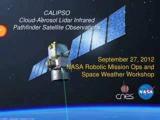
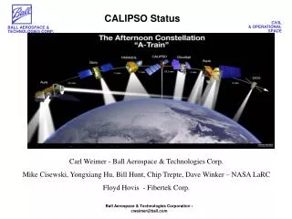
Development status of the CALIPSO lidar. Gary Wilson Ball Aerospace and Technologies Corp. CALIPSO is a pathfinder for the GTWS mission. Flight-qualified Nd:YAG lasers demonstrated to 2 10 9 pulses with active Q-Switch and KTP doubler

E N D
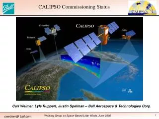
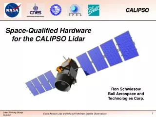
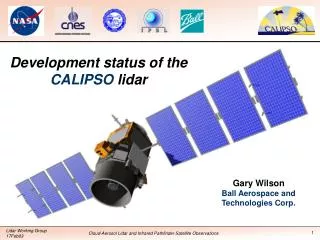
Development status of the CALIPSO lidar Gary Wilson Ball Aerospace and Technologies Corp.
CALIPSO is a pathfinder for the GTWS mission • Flight-qualified Nd:YAG lasers demonstrated to 2109 pulses with active Q-Switch and KTP doubler • Lightweight laser beam expanders with anti-feedback provision • 1-m beryllium telescope (Goodrich Danbury) • Flight-qualified PMT and APD detectors with low-noise preamps • High-speed space qualified analog-to-digital converters • Powerful, flight-qualified computer with fault tolerance (PowerPC™ 603R) • Auxiliary instruments for context imaging: Wide-field Camera (WFC) and Imaging Infrared Radiometer (IIR)
The payload includes three instruments Telescope Sunshade Wide Field Camera X-Band Antenna Star Tracker Assembly X-Band Transmitter Payload Controller Laser Electronics Unit Imaging Infrared Radiometer Lidar Receiver Electronics Integrated Lidar Transmitter Receiver Power Supply
Monolithic optical bench is kinematically mounted to Proteus platform Lidar Instrument Core Adjustable Boresight Mechanism APD PMTs Laser Radiator Optical Bench Laser Optics Modules Telescope Beam Expander Optics ILT (Integrated Lidar Transmitter) ILR (Integrated Lidar Receiver)
Color code: Complete In test In assembly Color code shows payload integration status Lidar Instrument Data Payload Controller VME BUS Telemetry (Housekeeping) Integrated Lidar Receiver Housekeeping MS-1553 Platform Interface Payload Processor Lidar Receiver Electronics GPS PPS 1064 Receiver Optics APD 532 // DRS (8) Sync Signal PMT System Interface 532 PMT Cmd/Status Low Voltage Power Supply Shutter/ Depolarizer Mechanism T0 Telescope Integrated Lidar Transmitter ANA (5) Boresight Mech Mechanism & Heater Control HLC (6) Power Relay BEO Laser-1 1064 nm 532 nm DRS (2) BEO Laser-2 BNR (5) Instrument Data Data Formatter/ Mass Memory WFC 620-670 nm Energy Software IIR Composite Structure (Housing, Bench, Lightshade) 12.05, 10.6, 8.65 mm Energy X-Band Transmitter Legend PPS – Pulse Per Second DRS – Digital Relay Status ANA – Analog Acquisitions HLC – High Level Commands BNR – Bus Non Regulated Filter Science Data System
Lasers & radiator are integrated and flight qualified Flight lasers (LOMs) & radiator have been qualified and integrated; the electronics unit (LEU, left) is in final qualification test. The LOMs are operated at 110 mJ per pulse at 532 nm and 1064 nm
Beam-expander optics (BEO) are delivered and tested BEO provides 13x (f=0.9) expansion with >98% reflectivity, laser hard coatings, and anti-narcissism features Beam expander testing and final-alignment performed with matching flight laser
Risk-reduction laser provided validation of design and contamination management • 2109 pulses demonstrated • Validated contamination-control and hermetic- sealing procedures • Verified KTP doubler operation and life • Established misalignment tolerance • 110 mJ per pulse each wavelength • 27.9 FWHM bandwidth at 532 nm • 8 mm-mrad beam quality • 3700:1 polarization purity
Receiver telescope and spectral filters are integrated and tested Beryllium telescope has fast primary and f/4.7 secondary; the unit was aligned in the Ball JWST Large-Optics Test Facility (LOTF) Thermal-tuned solid etalon provides 42 pm bandpass with 85% throughput; the unit was calibrated with the flight lasers
Flight detectors have completed characterization & calibration at Langley • Avalanche Diode (APD) • MOLA heritage design • 40% QE • 0.004 pW Hz -½ NEP • 2.5 MHz bandwidth • Photomultiplier (PMT) • LITE heritage design • 12.8% QE • 0.11 fW Hz-½ NEP • 2.5 MHz bandwidth
Flight electronics are complete and in system integration X-Band (80 Mbps) Transmitter includes matched Nyquist filters to eliminate conflict with the Deep Space Network The Lidar Receiver Electronics (LRE) and Receiver Power Supply (RPS) were used in flight detector calibration The Payload Controller is complete including the 480 MIPs computer & 64 Gb memory
Adjustable boresight & shutter mechanisms are complete The shutter-depolarizer mechanism was qualified and installed The Adjustable Boresight Mechanism (ABM) and launch-locks were qualified and are now being installed on the Lidar Core
Wide-Field Camera performance verified in High Accuracy Test Systems (HATS) • Based on CT-633 star tracker • Dark noise <15 e per sample • Linearity <5% departure to full 730 W m-2 sr-1 nm-1 spectral radiance • Bandpass filter 620-670 nm • Modified to RS-422 serial I/O bus
Imaging infrared radiometer is developed by SODERN • Based on Boeing micro-bolometer arrays • Mirror for 2-point calibration • 6464 snapshot array • 3 spectral channels sequential (8.65, 10.6, 12.05 m)
Composite housing, lightshade and wire harnesses in vac-bake cleaning Flight wire harness installation prior to vacuum tests Payload housing showing lightshade (rear) & WFC platform
Payload controller and command & control consoles used for SW testing 100% flight-like electronics Payload Controller Emulator System (PCES), left Instrumentation Test Operations Console (ITOC), right
Payload instrument simulators are complete and in-use The Payload Simulator (left) was used to verify instrument-to-spacecraft interfaces at Alcatel High-Fidelity Simulator (right) will be used for spacecraft software development and includes actual instrument computer and flight code
Launch planned for 4Q 2004 • Instrument delivery to Alcatel facility scheduled for 3Q 2003 • Spacecraft delivery to VAFB scheduled for 3Q 2004 • Ball & VAFB operations include atmospheric performance testing with cooperative lidars • Launch planned 4Q 2004 • Launch with CloudSAT on dual launch adapter fitting (DPAF) • Delta II 7420 launch vehicle • 3-m standard fairing