Traffic Light Behavior
Traffic Light Behavior. A. B. Car Sensors. IF A=1 AND B=0. Traffic Light Behavior. A. B. Car Sensors. Otherwise. IF A=1 AND B=0. Traffic Light Behavior. A. B. Car Sensors. Otherwise. IF A=1 AND B=0. Always. Traffic Light Behavior. A. B. Car Sensors. Otherwise.

Traffic Light Behavior
E N D
Presentation Transcript
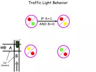
Traffic Light Behavior A B Car Sensors IF A=1 AND B=0
Traffic Light Behavior A B Car Sensors Otherwise IF A=1 AND B=0
Traffic Light Behavior A B Car Sensors Otherwise IF A=1 AND B=0 Always
Traffic Light Behavior A B Car Sensors Otherwise IF A=1 AND B=0 Always IF A=0 AND B=1 Otherwise
Traffic Light Behavior A B Car Sensors Otherwise IF A=1 AND B=0 Always Always IF A=0 AND B=1 Otherwise
Traffic Light Behavior A B Car Sensors Otherwise Note:Clock beats every 4 sec.So Light is Yellow for 4 sec. IF A=1 AND B=0 Always Always IF A=0 AND B=1 Otherwise
Traffic Light State Machine A B Car Sensors Otherwise Note:Clock beats every 4 sec.So Light is Yellow for 4 sec. IF A=1 AND B=0 Always Always IF A=0 AND B=1 Otherwise
Traffic Light Design • We’ve figured out the logical behavior of the Traffic Light in terms of a State Machine: • We know what the states are. • For each state, given any input,we know which state to go to next. • How do we build it?
Traffic Light Design • Thinking this through: • Our machine needs to:
Traffic Light Design • Thinking this through: • Our machine needs to: • Remember which state it is in (Memory)
Traffic Light Design • Thinking this through: • Our machine needs to: • Remember which state it is in (Memory) • Given the state it is in and input values, it must determine which state to go tonext (Logic)
Traffic Light Design • Thinking this through: • Our machine needs to: • Remember which state it is in (Memory) • Given the state it is in and input values, it must determine which state to go tonext (Logic) • And that’s all !
Traffic Light Design • Problem 1: • Remember which state it is in (Memory) • How do represent the states? • We could keep one bit of memory for whether Light A is Green or not, whether it is Yellow or not, … • This would take 6 bits of memory. • There is a much simpler way!
Traffic Light Design • Problem 1: • Remember which state it is in (Memory) • How do represent the states? • Answer: • Just number them (using binary numbers). • We have 4 states. • Call them 00, 01, 10, 11. • We (human designers) will keep track of what these names mean.
Traffic Light States Otherwise IF A=1 AND B=0 Light A Always Always IF A=0 AND B=1 Otherwise Light B
Traffic Light States Otherwise IF A=1 AND B=0 01 00 Light A Always Always IF A=0 AND B=1 11 10 Otherwise Light B
Traffic Light Design • Problem 2: • Given the state it is in and input values, it must determine which state to go tonext (Logic) • Answer:
Traffic Light Design • Problem 2: • Given the state it is in and input values, it must determine which state to go tonext (Logic) • Answer: • Build a Truth Table • Use Universal Method!
M1 M2 ABD1 D2Light A Red Light B Red … Traffic Light Behavior Build A Truth Table for next state / Output
Traffic Light Behavior Otherwise IF A=1 AND B=0 01 00 Light A Always Always IF A=0 AND B=1 11 10 Otherwise Light B
M1 M2 ABD1 D2Light A Red Light B Red … 0 0 1 0 0 1 1 0 Traffic Light Behavior Build A Truth Table for next state / Output
Traffic Light Behavior Otherwise IF A=1 AND B=0 01 00 Light A Always Always IF A=0 AND B=1 11 10 Otherwise Light B
M1 M2 ABD1 D2Light A Red Light B Red … 0 0 1 0 0 1 1 0 0 1 * * 1 0 1 0 Traffic Light Behavior Build A Truth Table for next state / Output
Traffic Light Behavior Otherwise IF A=1 AND B=0 01 00 Light A Always Always IF A=0 AND B=1 11 10 Otherwise Light B
M1 M2 ABD1 D2Light A Red Light B Red … 0 0 1 0 0 1 1 0 0 1 * * 1 0 1 0 1 0 0 1 1 1 0 1 Traffic Light Behavior Build A Truth Table for next state / Output
Traffic Light Behavior Otherwise IF A=1 AND B=0 01 00 Light A Always Always IF A=0 AND B=1 11 10 Otherwise Light B
M1 M2 ABD1 D2Light A Red Light B Red … 0 0 1 0 0 1 1 0 0 1 * * 1 0 1 0 1 0 0 1 1 1 0 1 1 1 * * 0 0 0 1 Traffic Light Behavior Build A Truth Table for next state / Output
Traffic Light Behavior Otherwise IF A=1 AND B=0 01 00 Light A Always Always IF A=0 AND B=1 11 10 Otherwise Light B
M1 M2 ABD1 D2Light A Red Light B Red … 0 0 1 0 0 1 1 0 0 1 * * 1 0 1 0 1 0 0 1 1 1 0 1 1 1 * * 0 0 0 1 0 0 0 0 0 0 1 0 … … … … … … … Traffic Light Behavior Build A Truth Table for next state / Output
Traffic Light Design • We understand how to represent which state the system is in (so we can store it in Memory) • We understand how the system can determine which state to go to next (Logic) • Let’s put it together…
Traffic Light Design Input: Sensor A Input: Sensor B
Traffic Light Design Current State D1 M1 2-bit Memory Register D2 M2 Write Sensor A Sensor B
Traffic Light Design Current State Next State 2-bit Memory Register Logic For Next State & Output Write Sensor A 6 Outputs: for eachLight Sensor B
Traffic Light Design Current State 2-bit Memory Register Logic For Next State & Output Write Sensor A 6 Outputs: for eachLight Sensor B
Traffic Light Design Current State 2-bit Memory Register Logic For Next State & Output Clock Sensor A 6 Outputs: for eachLight Sensor B
Design for Any State Machine Manybits Current State Memory Register Logic For Next State & Output Clock Inputs Outputs
State Machinesin Real Life • Elevator control systems • Car control systems • VCR’s • Alarm Clocks • Personal Computers • … Just about everything!
More Sophisticated Designs • Just add more states, more inputs, more outputs, more rules… • Example: Add a longer delay before Traffic Light changes fromYellowtoRed.(Say 8 seconds instead of 4.)
Traffic Light Behavior Otherwise IF A=1 AND B=0 Always Always Light A Always Always IF A=0 AND B=1 Otherwise Light B
More Sophisticated Designs • Note that the new “delay” states we added correspond to the SAME combinations of lights as other states (Red/Yellow). • The purpose of the new states is only to add delays. • Logical states need not correspond to different observable states of the machine!
More Sophisticated Designs • Can also add other State Machines!
More Sophisticated Designs • Example (Fairness): • We might want a separate Timer machine for the Traffic Light: • If cars keep coming, Light should decide after 3 minutes to switch lights. • A Timer is just a state machine that keeps counting beats of the Clock
Main State Machine More Sophisticated Designs Inputs Outputs Timer StateMachine
Computers! State Machines that you can program
Review • In designing state machines, we used: • Binary Representation (to represent states) • Memory (to store the current state) • Logic Circuits & Universal Method (to determine the next state) • In this way, we learned how to buildspecial-purpose digital systems(e.g. traffic lights)
General Purpose Computers • What makes a PC different? • Today your PC can’t play Final Fantasy X. • Tonight, you buy the Final Fantasy X CD-ROM • Tomorrow your PC can play the game! • PC’s are general-purpose computers. • Realize state machines for traffic lights, digital cameras, VCR’s, … • You can write a program (software) to control the circuitry (hardware) of a general purpose computer
The Stored Program • Idea is simple: • Build a machine that can execute certain instructions. • Then, write down different lists of instructions (programs) to accomplish different things. • One program plays an adventure game • Another program lets you write papers • Another lets you surf the Web
Programming • Using software to control hardware • Hardware is fixed circuitry • Software is instructions to the processor to control the inputs to the fixed circuitry • Inputs to the hardware are of 2 types • Data • Program • We don’t differentiate • Both are stored in computer’s memory
History of ProgrammableMachines • First “programmablesystem” was the early printing process developed in China circa 800 C.E. • First “program” wasperhaps Chinese translation ofBuddhist Canon(the Tipitaka)
History (cont.) • Gutenberg’s Printing Press(circa 1450) • Main Contribution: • Just a few “basic instructions” (smalleralphabet size) suffice.