Download
1 / 15
150 likes | 260 Vues
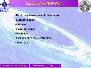
Layout of the TOF Wall. Basic requirements and boundaries Modular design Hit rates Read-out chain Radiation Placement of the electronics Summary. Basic requirements. Full system resolution : s T ~ 80 ps , distance to targ. ~ 10 m, area ~ 150 m 2

E N D
Layout of the TOF Wall • Basic requirements and boundaries • Modular design • Hit rates • Read-out chain • Radiation • Placement of the electronics • Summary K.Wisniewski Uni.Heidelberg
Basic requirements • Full system resolution : sT ~ 80 ps , distance to targ. ~ 10 m, area ~ 150 m2 • Eff. > 95 % , acceptable cross-talk, charge-sharing and space resolution • Rate capability ~ 20 kHz/cm2 • Occupancy < 5 % => pile-up, double hit < 5% • Low power electronics (~75.000 channels), free running, ~30 ps K.Wisniewski Uni.Heidelberg
Layout of the TOF Wall In order to accommodate the different granularities as a function of the polar angle, four different regions were defined: 1m 1,5m • Pad/narrow strip region: 2.5 x 2,5 cm2 (rate: 20 - 8 kHz/cm2 , area: 12 m2 , #SM: 8) • Strip/narrow strip region: 25 x 1 cm2 (rate: 8 - 3.5 kHz/cm2 , area: 24 m2 , #SM: 16) • Strip region: 50 x 1 cm2 (rate: 3.5 – 1.5 kHz/cm2, area: 36 m2 , #SM: 24) • Strip region: 50 x 1 cm2 (rate: 1.5 – 0.5 kHz/cm2 , area: 48 m2 , #SM: 32) Questions to be answered : rate/resolution capability, granularity K.Wisniewski Uni.Heidelberg
Modular design 1 SM with 120 pad RPC active area is not overlaped active area: 5 x 25 cm2 (~5 cm2 / ch) read out: single ended channels: 120 x 20 = 2400 / SM glass: low resistive / ceramics 1 SM with 20 strip RPC active area slightly overlaped active area: 32 x 25 cm2 (~25 cm2 / ch) read out: both sides channels: 20 x 32 x 2 = 1280 / SM glass: low resistive 1 SM with 10 strip RPC active area slightly overlaped active area: 32 x 50 cm2 (~50 cm2 / ch) read out: both sides channels: 10 x 32 x 2 = 640 / SM glass: low resistive 1 SM with 10 strip RPC active area slightly overlaped active area: 32 x 50 cm2 (~50 cm2 / ch) read out: both sides channels: 10 x 32 x 2 = 640 / SM glass: float (+ warming up) In total ~ 75000 channels K.Wisniewski Uni.Heidelberg
13 cm Example pad / strip for the hottest part Pad MRPC developed at Tsinghua Ceramics RPC developed at Rosendorf Pad structure of the pickup electrode Pad:2 cm x 2 cm K.Wisniewski Uni.Heidelberg
Mean hit rate / channel MinBias Au+Au @ 25 AGeV, 10 MHz interaction rate 10-2 hits / event /channel => double hit ~ 1% K.Wisniewski Uni.Heidelberg
FrontEnd configuration SYSCORE FEET PADI x 8 chan. In total ~ 700 ROCs K.Wisniewski Uni.Heidelberg
Data rate / GET4 GET4 message size : 25 bits/hit, other message (epoch): ~40 kHz K.Wisniewski Uni.Heidelberg
Data rate / ROC 2 R2F connectors / ROC => 2x4 x 2x7 = 112 channels / ROC (2x14 GET4/ROC) ROC message size : 50 bits / hit 20% overhead More GET4 / ROC is possible & necessary 2.5 Gbit/s output of the opt. link K.Wisniewski Uni.Heidelberg
Radiation – CMB Year WFJ. Müller K.Wisniewski Uni.Heidelberg
Total Integrated Dose @ TOF FLUKA simulations PADI will get a few kRad / y Is not be a problem even for FPGA Tested (KIP) up to 700 kRad Effects partially anneal with time K.Wisniewski Uni.Heidelberg
Single-Event Upsets – FPGA scrubbing • Realistic scrubb. speed : 1 bit / 2 ns (~12ms / ~80Hz ) • Tests (KIP) show that only ~1/3 of all SEUs actually affect the running design • Redundancy implementation can handle at least 1 functional error per scrubbing cycle • → 3 SEUs per scrubbing cycle (12ms) affordable • → max. SEU-Rate: 3/12ms = 250/s • Cross section for proton SEUs: < 5*10-13 cm²/bit • SEU-Rate = #(bits) * (cross-section) * (flux) • #(bits for Virt4-FX20) ~6*106 bit • ↔ max. flux ~ O(107) protons/(cm²*s) • Heavy ion cross section significantly higher • (up to ~10-8 cm²/bit) • Larger FPGA => longer scrubb. cycles K.Wisniewski Uni.Heidelberg
80 80 80 80 80 80 80 80 80 80 80 80 80 80 80 80 80 80 80 80 160 160 160 160 160 80 80 80 80 160 300 300 300 160 80 80 80 80 160 300 300 160 80 80 80 80 160 300 300 300 160 80 80 80 80 160 160 160 160 160 80 80 80 80 80 80 80 80 80 80 80 80 80 80 80 80 80 80 80 80 80 80 80 + 80 80 + 80 80 + 80 80 + 80 80 + 80 80 80 80 80 160 160 160 160 160 80 80 80 + 80 160 150 150 150 150 150 160 80 + 80 80 + 80 160 150 150 160 80 + 80 80 + 80 160 150 150 160 80 + 80 80 + 80 160 150 150 160 80 + 80 80 + 80 160 150 150 150 150 150 160 80 + 80 80 80 160 160 160 160 160 80 80 80 80 80 + 80 80 + 80 80 + 80 80 + 80 80 + 80 80 80 Placement of the read-out electronics FEET-PADI on the detector FEET-TDC may be shifted ROC more outside, but cabling can be an issue K.Wisniewski Uni.Heidelberg
Summary • Areas of different requirements defined • Modular design, different granuralieties, technologies • Double hit, occupancy not an issue • Rate capability/resolution of the existing RPC- prototypes not obvious • Read-out chain being prototyped KIP and tested KIP,GSI ; final design not there yet • Data rates under control • Radiation on the electronics can be coped with, proper/redundand design necessary • Placement of the electronics dependant rather on cabling/cost/in-beam material budget K.Wisniewski Uni.Heidelberg
Layout of the TOF Wall K.Wisniewski Uni.Heidelberg