Download
1 / 9
90 likes | 217 Vues
This study focuses on the detailed arrangement and mounting of the trim coil, currently positioned beneath the toroidal field (TF) coils. The analysis includes a top view perspective showcasing a 4-turn, ½” square conductor winding, emphasizing the simplicity and efficiency of the flat coil design. Step-by-step methodologies are outlined for proper installation and alignment, ensuring optimal performance and functionality of the coil system. Each stage, from Step 3A through Step 10, is meticulously documented for clarity and precision.

E N D
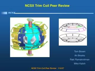
Trim coil arrangement currently shown is mounted off the underside of the TF coils.
28.8 27.3 Top View
4-turn, ½” square conductor Winding 4-turn on the flat coils is straight forward.
Step 3A Step 4 Step 6 Step 5
Step 7 Step 8 Step 10 Step 9