Frequency Response in Electrical Circuits
Explore transfer functions, decibel scale, Bode plots, resonance circuits, passive & active filters, PSpice usage for frequency response analysis. Apply knowledge to radio receivers and touch-tone telephones.

Frequency Response in Electrical Circuits
E N D
Presentation Transcript
Chapter 14Frequency Response Chapter Objectives: • Understand the Concept of Transfer Functions. • Be Familiar with the Decibel Scale. • Learn how to make Bode Magnitude and Phase plots. • Learn about series and parallel resonant RLC circuits. • Know Different Types of Passive and Active Filters and their Characteristics. • Understand the use of scaling in circuit analysis. • Be Able to use PSpice to obtain frequency response. • Apply what is learnt to radio receiver and touch-tone telephone. Huseyin Bilgekul Eeng 224 Circuit Theory II Department of Electrical and Electronic Engineering Eastern Mediterranean University
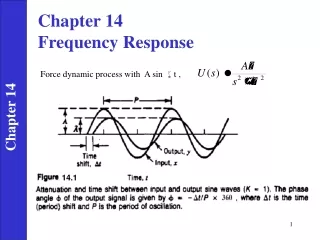
FREQUENCY RESPONSE What is Frequency Response of a Circuit? It is the variation in a circuit’s behavior with change in signal frequency and may also be considered as the variation of the gain and phasewith frequency.
TRANSFER FUNCTION • The transfer function H() of a circuit is the is the frequency dependent ratio of the phasor output Y() to a phasor input X(). • Considered input and output may be either the current or the voltage variable. • 4 types of possible transfer functions.
TRANSFER FUNCTION of Low-pass RC Circuit R=20 kΩC=1200 pF At low frequencies At high frequencies Magnitude plot for a low-pass filter
TRANSFER FUNCTION of Low-pass RC Circuit Phase plot for a low-pass filter R=20 kΩC=1200 pF At low frequencies At high frequencies
TRANSFER FUNCTION ofHigh-pass RC Circuit R=20 kΩC=1200 pF At high frequencies At low frequencies Magnitude plot for a high-pass filter
TRANSFER FUNCTION ofHigh-pass RC Circuit Phase plot for high-pass filter R=20 kΩC=1200 pF Magnitude plot for a high-pass filter At high frequencies At low frequencies
Frequency Response of the RC Circuit a) Time Domain RC Circuit b) Frequency Domain RC Circuit
Drawing Frequency Response of RC Circuit Low Pass Filter a) Amplitude Response b) Phase Response • The frequency value of ois of special interest. • Because output is considerable only at low values of frequency, the circuit is also called a LOW PASS FILTER.
TRANSFER FUNCTION • The transfer function H() can be expressed in terms of its numerator polynomial N() and its denominator polynomial D(). • The roots of N()=0 are called ZEROS of H() (j=z1, z2, z3, ….).Similarly The roots of D()=0 are called POLES of H() (j=p1, p2, p3, ….). A zero as a root of the numerator polynomial, results in a zero value of the transfer function. A pole as a root of the denominator polynomial, results in an infinite value of the transfer function.
0.5Vx 0.5Vx Vx Vx