ATLAS EXPERIMENT INTEGRATION TASK: SPACE MANAGEMENT
240 likes | 250 Vues
Learn about the ATLAS integration task at CERN, involving CAD system upgrades, space management, envelope definition, and integration challenges from 1995 to present.

ATLAS EXPERIMENT INTEGRATION TASK: SPACE MANAGEMENT
E N D
Presentation Transcript
ATLAS EXPERIMENT INTEGRATION TASK: SPACE MANAGEMENT Tatiana Klioutchnikova 05/06/2014
Beginning of ATLAS integration task • Year 1995: creation of Atlas Integration Team ( team leader and 3-4 designers) • First tasks of the team: • Work on global layout • Definition of envelopes and interfaces • Routing of services • Access structures • Year 1998: creation of TDR “Technical Co-ordination” that described Naming conventions, Organizational matters, • Mechanical integration, Services integration, Installation and many other related matters.
Use of CAD systems for the mechanical integration • 1995 – 2006 - EUCLID CAD system used as basic at CERN for design and integration of LHC detectors (EUCLID CAD system was inherited from LEP period and became out of date quickly after beginning of ATLAS integration. It did not have enough functionalities for the integration of big and complex systems like ATLAS) • 2000 – search for future CAD system for mechanical design at CERN started. EUCLID authors announced the end of further development and gradual stop of support • 2003 – Catia V5 CAD system was recommended to become a basic CAD system at CERN • 2004 – ATLAS model transfer to Catia V5 started by a team from Georgia, Tbilisi university • End 2004 – First checks for conflicts have shown that Catia V5 is more fast and efficient compare to Euclid system ( use of DMU Space Analysis ) • 2005 – Complete check for conflicts and clearances procedure was adopted for all designed equipment • 2007-2008 massive conversion of 3D models to Catia V5 format. Very painful process that caused some degradation of data • Since 2008 use of Catia V5 and SmarTeam for database management
CAD data for Atlas (June 2007) • Integration (layouts, services, studies of installation, envelopes..) 5000 • Inner Detector 3700 • Magnets 1200 • Calorimeter LAr 700 • Calorimeter Tile 1100 • Muon system 3300 • Beam pipe 1200 • Structures (access and support, SW, BW, shieldings…) 5900 • Infrastructure (ventilation, cooling, gas..)4200 28 000 modelsand drawings in total created and stored in 84 Euclid databases organized by sub-projects ( models mean assemblies, not small parts) 106 designers have been registered in ATLAS EUCLID databases from 1995 to 2007. Time constrains and low speed of conversion did not allow to make a total conversion. So models for the translation to Catia have been selected and tagged manually by few designers.
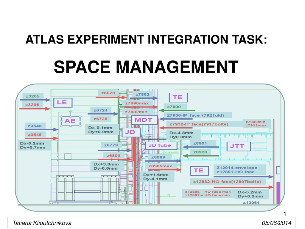
Space management • Layout definition • Envelope space attribution for each sub-system • Every sub-system is using only attributed space for their design • Each request of additional space is discussed with TC • TC organize resolution of conflicts with neighbouring sub-systems • Modification of all concerned envelopes. This is a process of iterations, the envelopes are in constant evolution during their lifetime. • Engineering change notice if several sub-systems involved • Fabrication of detector parts: survey and check dimensions compare to envelope • Integration and Installation of detector parts: survey and check dimensions compare to envelope • Simultaneous study of services routing and estimation of space for services between envelopes • access and support structures design • Accessibility checks • Installation studies • Scenarios of detector opening and closing for maintenance and upgrade: check for conflicts
Layout of detectors for ATLAS – one of basic documents for the integration
Barrel Toroid magnet and Feet Rail system – main support structure for other detector parts.
2. Envelopes Definition • The individual envelope of a system corresponds to the maximum space (volume) allocated to a system itself in its own local axis system. • Individual Envelope definition: • Nominal dimensions + manufacturing/assembly tolerances + maximum deformation under normal and faulty loading cases. • The global envelope corresponds to the volume occupied by a system after its positioning and adjustment inside the detector. • Global Envelope definition: • Individual envelope + Global assembly tolerance (when applicable) + positioning and adjustment tolerances.
Individual envelope definition for one of Barrel Toroid coils
Example of the simplified envelope model at the beginning of integration , detailed model and real assembly in the cavern of the services tower for the End-Cap Toroidal Magnet of ATLAS experiment.
Detailed Description The change proposed is to increase the Toroid Barrel Inner radius by 25 mm (50 mm on diameter) in order to gain space between Muon BIS chambers and the Barrel and End Cap Calorimetry. The vacuum vessels nominal positions are provided in CEA drawing “ ATLAS Barrel toroid Assembly – Front View” 9B 2900 - DM 0000 001(see Annex A). The vacuum vessel inner radius is 4720 mm nominal dimension, will increase to 4745 mm The vacuum vessel outer radius is 10040 mm nominal dimension, increase to 10065 mm
Interpretation of survey results: Deviations from theoretical coordinates BT06 BT04 20.9; 17.5 21.2; 11.9 15.4; 6 17.6; 10.7 4.6; -3.9 16.8; 10.2 5.4; 1 18.7; 15.3 17.5; 10.5 15.5; 10.9 2.1; -2.8 11.6; 6 14.1 7.9 14.1 15.9 1.5 1.1 2.6 2.8 8.5 15.3 13.6 3 16.3 3.4 6.5 2.3 13.8; 9.5 20.9; 11.5 23.3; 14.2 18.3; 9.3 18.7; 8.3 0.3; -5.6 16.6; 11.2 12.4; 9.1 BT08 19.5; 13.2 17.8; 7.5 BT02 5.3; -2.5 15.6; 3.5 6.4; 0 9.2; 0.9 14.1; 1.7 11.6; 0.3 8.8 11.8; -4.2 10; 3.1 8.6 12.1; 2.8 7.7; 3.1 9.7 7.8 6.1 18.4; 2.9 12.5; -15 11 0.5 5.4 6; -1 8.2; 2.4 2.3 11.1 4.9 4.8; -1.3 79.1; 2.6 9.4; -26.9 9.2; -19.7 0.4 5.4 6.2 18.6; 3.9 2.1 6.8 12.3; -5 10.7; 9.4 18.1; 9.5 3.9; -10.3 4.4; -2.8 11.5; 6.3 5.2; -0.2 5.5; 1.1 0.2; -5.8 7.7; -9.7 19.8; 3 11.1; -6.2 5.9; -3.1 0.5 5.5 17; -2 13.8; -1.6 8.2 8.7 3.6 0.8 13.2; 5.9 5.5 4; -3.5 3.2; 1.4 7.3 4.6 13.9; 1 6.2; -0.4 13.2 13.4; 0.1 5.9 6.8; 1 2.6; -10.7 1.2 3 12.5; 2.6 9.9 6.9; 6.3 4 3.6; 1.7 17; -3 1.1; -9.1 1.7 2; -5.2 14.5; 10.7 BT10 BT16 5; -0.1 16.8; 1.4 6; 1.8 1.1; -1.1 8.5; -34.9 1.4; -8.8 10.3; 1.1 19; 2.1 7.8; -2.1 9.8; 1.8 6.3; 2.7 8.1; 0.3 1.9 0.8 22.1; 10.5 0.3 7.5 3.9 5.8 7.3 2.9 2.5 5.2 3.4 8 4.5 Y 2.7 4.7 5.3 8.5; 4.3 2.4 0.4; -0.2 17.2 28.2; 15.6 5.2; -10.5 5.3; -13.9 10.5; 1.7 14.1; 5.2 9.6; -12 Note: For envelope points (maximum deviation; minimum deviation) X 9.7; 7.9 13.4; 1.7 BT12 BT14
Example of checking for conflicts using 3D models : more than 700 corridors for muon alignment system cross the detectors, structures and services to define precise positioning of almost 2000 muon chambers in ATLAS.
6 4 2 8 10 16 US USA 12 14
Sector 12 Z=0 Ring 1 Ring 2
All Sectors – ring 2 – Side A and C 1 Bolt concerned
Year 2003 - beginning of the installation in the cavern. Design office becomes bigger. 15-17 designers working on different systems in parallel. Very difficult to check all models for conflict. Solution has been found with help of Georgian team that worked at distance checking all new created and modified models with the whole detector model. They used Catia DMU module for these checks. We received every day hundreds pages of reports that we had to check.
Example of a clash report generated by Catia Every new designed model now has to pass through the Catia check before being accepted. After the check the designers get the reports of clashes and clearances and modify the models if necessary.
Use of SCAN SCAN is very helpful to make corrections of the models and to create as-installed versions.
Check of End-Cap Toroid installation using dynamic simulation with 3D models Real End-Cap Toroid installation in ATLAS cavern.
Outcome of our experience • Using of CAD system for the big and longterm project: be prepared for the change of the system from the beginning. It means very good organization of models in database. • Product lifecycle management is very important. Models should have correct status: released, obsolete, in work, envelope, nominal, as-built, simplified, etc. It will help during life time of the project and for the migration to a new system. • It is recommended to provide automatically in the database some neutral formats like pdf for drawings and step for 3D • In complex systems check for conflict is recommended after every modification. A process should be established for all designers, especially during massive design process in a big team. • A lot of attention to the interfaces between envelopes • All displacements should be taken into account during checks after modifications • Scan is a powerful tool to create “as-built” models • … • Not possible to mention all important issues in one presentation