Wind Energy Technology
Explore the orientation, advantages, and disadvantages of vertical and horizontal axis wind turbines, including lift vs. drag, airfoil nomenclature, performance factors, pitch vs. stall control, rotor solidity, Betz Limit, and the impact of the number of blades.

Wind Energy Technology
E N D
Presentation Transcript
Wind Energy Technology What works & what doesn’t
Orientation Turbines can be categorized into two overarching classes based on the orientation of the rotor Vertical AxisHorizontal Axis
Advantages Omnidirectional Accepts wind from any angle Components can be mounted at ground level Ease of service Lighter weight towers Can theoretically use less materials to capture the same amount of wind Disadvantages Rotors generally near ground where wind poorer Centrifugal force stresses blades Poor self-starting capabilities Requires support at top of turbine rotor Requires entire rotor to be removed to replace bearings Overall poor performance and reliability Have never been commercially successful Vertical Axis Turbines
Lift vs Drag VAWTs Lift Device “Darrieus” • Low solidity, aerofoil blades • More efficient than drag device Drag Device “Savonius” • High solidity, cup shapes are pushed by the wind • At best can capture only 15% of wind energy
VAWT’s have not been commercially successful, yet… Every few years a new company comes along promising a revolutionary breakthrough in wind turbine design that is low cost, outperforms anything else on the market, and overcomes all of the previous problems with VAWT’s. They can also usually be installed on a roof or in a city where wind is poor. WindStor Mag-Wind WindTree Wind Wandler
Capacity Factor Tip Speed Ratio
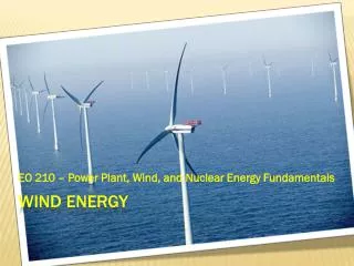
Horizontal Axis Wind Turbines • Rotors are usually Up-wind of tower • Some machines have down-wind rotors, but only commercially available ones are small turbines
Active vs. Passive Yaw • Active Yaw (all medium & large turbines produced today, & some small turbines from Europe) • Anemometer on nacelle tells controller which way to point rotor into the wind • Yaw drive turns gears to point rotor into wind • Passive Yaw (Most small turbines) • Wind forces alone direct rotor • Tail vanes • Downwind turbines
Airfoil Nomenclaturewind turbines use the same aerodynamic principals as aircraft
Lift & Drag Forces α = low • The Lift Force is perpendicular to the direction of motion. We want to make this force BIG. • The Drag Force is parallel to the direction of motion. We want to make this force small. α = medium <10 degrees α = High Stall!!
ΩR Ωr α V V VR = Relative Wind Apparent Wind & Angle of Attack α = angle of attack = angle between the chord line and the direction of the relative wind, VR . VR = wind speed seen by the airfoil – vector sum of V (free stream wind) and ΩR (tip speed).
ΩR V TSR = Tip-Speed Ratio ΩR R Tip-speed ratio is the ratio of the speed of the rotating blade tip to the speed of the free stream wind. There is an optimum angle of attack which creates the highest lift to drag ratio. Because angle of attack is dependant on wind speed, there is an optimum tip-speed ratio Where, Ω = rotational speed in radians /sec R = Rotor Radius V = Wind “Free Stream” Velocity
Performance Over Range of Tip Speed Ratios • Power Coefficient Varies with Tip Speed Ratio • Characterized by Cp vs Tip Speed Ratio Curve
Twist & Taper • Speed through the air of a point on the blade changes with distance from hub • Therefore, tip speed ratio varies as well • To optimize angle of attack all along blade, it must twist from root to tip
Pitch Control vs. Stall Control • Pitch Control • Blades rotate out of the wind when wind speed becomes too great • Stall Control • Blades are at a fixed pitch that starts to stall when wind speed is too great • Pitch can be adjusted for particular location’s wind regime • Active Stall Control • Many larger turbines today have active pitch control that turns the blades towards stall when wind speeds are too great
Airfoil in stall • Stall arises due to separation of flow from airfoil • Stall results in decreasing lift coefficient with increasing angle of attack • Stall behavior complicated due to blade rotation
Rotor Solidity Solidity is the ratio of total rotor planform area to total swept area Low solidity (0.10) = high speed, low torque High solidity (>0.80) = low speed, high torque R a A Solidity = 3a/A
Betz Limit All wind power cannot be captured by rotor or air would be completely still behind rotor and not allow more wind to pass through. Theoretical limit of rotor efficiency is 59% Betz Limit Rotor Disc Rotor Wake
Number of Blades – One • Rotor must move more rapidly to capture same amount of wind • Gearbox ratio reduced • Added weight of counterbalance negates some benefits of lighter design • Higher speed means more noise, visual, and wildlife impacts • Blades easier to install because entire rotor can be assembled on ground • Captures 10% less energy than two blade design • Ultimately provide no cost savings
Number of Blades - Two • Advantages & disadvantages similar to one blade • Need teetering hub and or shock absorbers because of gyroscopic imbalances • Capture 5% less energy than three blade designs
Number of Blades - Three • Balance of gyroscopic forces • Slower rotation • increases gearbox & transmission costs • More aesthetic, less noise, fewer bird strikes
Blade Composition Wood Wood • Strong, light weight, cheap, abundant, flexible • Popular on do-it yourself turbines • Solid plank • Laminates • Veneers • Composites
Blade CompositionMetal • Steel • Heavy & expensive • Aluminum • Lighter-weight and easy to work with • Expensive • Subject to metal fatigue
Blade ConstructionFiberglass • Lightweight, strong, inexpensive, good fatigue characteristics • Variety of manufacturing processes • Cloth over frame • Pultrusion • Filament winding to produce spars • Most modern large turbines use fiberglass
Hubs The hub holds the rotor together and transmits motion to nacelle Three important aspects • How blades are attached • Nearly all have cantilevered hubs (supported only at hub) • Struts & Stays haven’t proved worthwhile • Fixed or Variable Pitch? • Flexible or Rigid Attachment • Most are rigid • Some two bladed designs use teetering hubs
Direct Drive Enercon E-70, 2.3 MW (right) Drive Trains Drive Trains transfer power from rotor to the generator • Direct Drive (no transmission) • Quieter & more reliable • Most small turbines • Mechanical Transmission • Can have parallel or planetary shafts • Prone to failure due to very high stresses • Most large turbines (except in Germany) GE 2.3 MW (above) Multi-drive Clipper Liberty 2.5 MW (right)
“The rotor is the single most critical element of any wind turbine… How a wind turbine controls the forces acting on the rotor, particularly in high winds, is of the utmost importance to the long-term, reliable function of any wind turbine.” Paul Gipe Micro Turbines May not have any controls Blade flutter Small Turbines Furling (upwind) – rotor moves to reduce frontal area facing wind Coning (downwind) – rotor blades come to a sharper cone Passive pitch governors – blades pitch out of wind Medium Turbines Aerodynamic Stall Mechanical Brakes Aerodynamic Brakes Rotor Controls
Towers • Monopole (Nearly all large turbines) • Tubular Steel or Concrete • Lattice (many Medium turbines) • 20 ft. sections • Guyed • Lattice or monopole • 3 guys minimum • Tilt-up • 4 guys • Tilt-up monopole