Download
1 / 34
370 likes | 598 Vues
Learn the types and working principles of clutches, including positive, single-plate, multi-plate, cone, and centrifugal clutches, as well as the importance and types of couplings used in vehicle applications.

E N D
Brakes, Clutches and Couplings Prepared by: guided by: CHAVDA PARAKRAM(130540106017) prof. hiren H. makwana MANIYAR DHARMI(130540106071) TANNA HARSHIL(130540106117) PANCHANI DENISHA(130540106077)
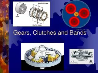
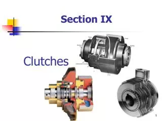
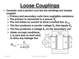
Purpose • A clutch is designed with the following requirements • Allow the vehicle to come to a stop while the transmission remains in gear • Allow the driver to smoothly take off from a dead stop • Allow the driver to smoothly change gears • Must not slip under heavy loads and full engine power
Types of clutch 1) Positive clutches • When positive drive is required then positive clutches are used. The simplest type of positive clutch is the jaw clutch which transmits the torque from one shaft to another shaft through interlocking jaws.
Single plate clutch Single plate clutch • It consists of various elements • pressure plate, • friction plate (clutch plate), • driving shaft, • splined driven shaft, • splined hub, • brass bush etc.
It consists of various elements, such as pressure plate, friction plate (clutch plate), driving shaft, splined driven shaft, splined hub, brass bush etc.
Friction plate has a ring of friction material on either side. Friction plate is attached to splined hub which is free to slide axially on splined driven shaft and rotates along with driven shaft. • The spring is placed between pressure plate and cover. Brass bush is press fitted inside the pressure plate so that it can rotate freely on driven shaft.
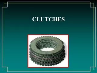
Multi plate clutch • It consists of two sets of plates the driving plates and driven plates arranged alternately, driving shaft, spring, splined driven shaft etc.
It consists of more than one driving as well as driven plates. So the number of pair of contacting surfaces is more than two.
Cone clutch • It consists of driving shaft, splined driven shaft, outer cone (cup), inner cone (cone), helical compression spring etc. The outer cone (cup) is keyed to the driving shaft and inner cone is free to slide axially on the splined driven shaft.
To engage the clutch axial force is provided by a helical compression spring. Clutch is disengaged by means of fork fitted in shifting collar or groove on the outer surface of cone, leather, cork or asbestos is used as friction lining.
Centrifugal clutch • It is works on the principle of centrifugal force. Centrifugal force is increases with the increase in speed.
It consists of spider having radial guide, sliding shoes, helical tension springs co-axial drum • The spider having four equally spaced radial guides is keyed to the driving shaft. Sliding shoes can slide radially in guides. • The sliding shoes are covered with frictional material from outer side. These shoes are held against spider on driving shaft by helical tension springs and all these assembly is enclosed in coaxial drum which is mounted on driven shaft.
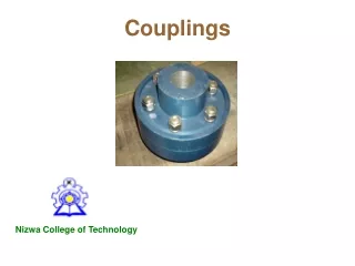
Coupling • Shafts are mostly available up to 7 meter length due to transport difficulty. To get a greater length, it is necessary to joint two or more pieces of the shaft using coupling. • Purposes of Coupling used are, • To connect shafts of motor and generator which are manufactured separately and to provide for disconnection for repairs. • To reduce the transmission of shock loads from one shaft to another. • To allow misalignment of the shaft or to introduce mechanical flexibility. • To introduce protection against overloads.
Types of couplings (1) Rigid coupling • It is used to connect two shafts which are perfectly in axial alignment. These couplings do not allow any relative rotation between the two shafts. • There are basic three types of rigid coupling as follows, • Sleeve or muff coupling • Clamp or split muff or compression coupling
(2) Sleeve or Muff coupling • Construction • This is the simplest type of rigid coupling. It is made from cast iron and very simple to design and manufacture. It consists of a hollow cylinder (muff) whose inner diameter is the same as diameter of the shaft.
The hollow cylinder (muff) is fitted over the ends of the two shafts with the help of taper sunk key. A key and sleeve (muff) useful to transmit rower from one shaft to the other shaft. It has no projecting parts.
3) Split muff coupling (clamp coupling) Construction • In this coupling, the muff or sleeve is made into two halves parts of cast iron and they are join together by bolts as shown in Figure. Both the halves are held together by means of M.S stud OR nut/Bolts.
(c) Flange coupling • There are basic two types, • (1) Unprotected type flange coupling • The projected portion of one of the flange and corresponding recess on other flange are help to bring the shafts into line and to maintain alignment.
(2) Protected type flange coupling • In order to prevent catching clothes of workmen in coupling the flange is provided with a shroud which shelters the bolt head & nuts . This coupling is called protected type flange coupling.
(2) Flexible couplings • This coupling is used to protect the driving and driven machine members against harmful effects produce due to misalignment of shafts, vibration, and sudden shock load or shaft expansion. • There are basic three types of flexible coupling as follows, • Bushed pin type flange coupling • Oldham coupling • Universal coupling
a) Bush pin type flange coupling • This is a modified form of protected type flange coupling • This type of coupling has a pins and it work as a coupling bolts. The rubber or leather bushes are used over the pins. The coupling is having two halves are dissimilar in construction. The pins are rigidly fastened by nuts to one of the flange and kept loose in the other flange.
(b) Oldham’s coupling • Construction • It consists of two flanges A and B with slots and a central floating disc as shown in fig. • Use • Connecting two parallel shafts but not in alignment, and their axes are at small distance apart.
(c) Universal coupling • Construction • It consists of two similar forks keyed on the ends of the two shafts. These two forks are assembled to a central block by pin. A central block having two arms at right angle to each other.
Brakes • Brake is a device by means of which an artificial frictional resistance is applied to a moving body in order to retard or stop the motion of a body. • During braking process, the brake absorbs either kinetic energy or potential energy or both by an object.
(a) Single block or shoe brake • Construction • It consists of blocks which are pressed against the surface of a rotating drum by means of lever. • The friction between friction lining on the block and drum retards the rotation of the drum. The block or shoe is made up of softer material than the rim of the drum. • The material of the block for light and slow vehicles is wood and rubber and for heavy and fast vehicles it is cast steel.
b) Pivoted block brake • Construction • A pivoted block brake is shown in figure 11.15. Unlike single block brake, in this the shoe is pivoted to lever to get uniform wear.
(c) Double block or shoe brake • This load produces the bending of the shaft. It can be prevented by using a double block or shoe brake having two blocks on the two sides of the drum.
(B) Band brake • Construction • It consists of a rope, belt or flexible steel band lined with frictional material which is wrapped partly round the drum. • Working • When band is pressed against the external surface of drum, the frictional force between drum and band will induce braking torque on the drum. • There are two types of band brake, • (a) Simple band brake • (b) Differential band brake
(a) Simple band brake • Construction • In this brake one end of the band is attached at the fulcrum of the lever while the other end is at a distance 'b' from fulcrum.
(b) Differential band brake • Construction • In a differential band brake, neither end of the band is attached to the fulcrum of the lever. The two ends of band are attached to the two points on opposite side of the fulcrum as shown in figure • The lever AOC is pivoted at fulcrum '0' and two ends of band are attached at points A and B.
(c) Band and block brake • Construction • It consists of number of wooden blocks fixed inside a flexible steel band.
(C) Internal expanding shoe brake • It consists of two semicircular shoes S1 and S2 pivoted at the fixed fulcrum O1 and O2 respectively. The outer surfaces of the shoes are lined with friction material • One end of the shoe is pivoted at fulcrum while the other end is subjected to the actuating force. The actuating force on both the shoes is applied by hydraulic cylinder or cam mechanism.