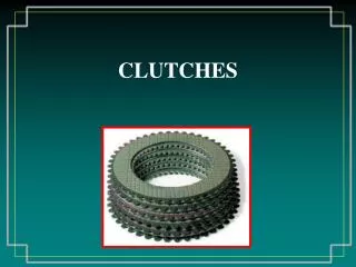
CLUTCHES
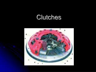
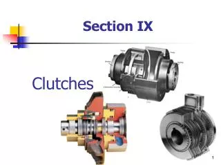
121. CLUTCHES. Figure 121-1 Typical automotive clutch assembly showing all related parts. (Courtesy of LUK ).


CLUTCHES
E N D
Presentation Transcript
121 CLUTCHES
Figure 121-1 Typical automotive clutch assembly showing all related parts. (Courtesy of LUK )
Figure 121-2 (a) When the clutch is in the released position (clutch pedal depressed), the clutch fork is applying a force to the throwout (release) bearing, which pushes on the diaphragm spring, releasing the pressure on the friction disc.
Figure 121-2 (b) When the clutch is in the engaged position (clutch pedal up), the diaphragm spring exerts force on the clutch disc, holding it between the flywheel and the pressure plate.
Figure 121-3 The transmission has just been removed. Note that this type of transmission incorporates the bell housing, which was therefore removed at the same time as the transmission. The clutch fork and throwout (release) bearing also came off together. All that remained attached to the engine was the flywheel, clutch disc, and pressure plate.
Figure 121-5 A hydraulic clutch linkage uses a master cylinder and a slave cylinder.
Figure 121-6 A typical clutch master cylinder and reservoir mounted on the bulkhead on the driver’s side of the vehicle. Brake fluid is used in the hydraulic system to operate the slave cylinder located on the bell housing.
Figure 121-7 A racing or high-performance clutch disc lacks the features of a stock clutch disc that help provide smooth engagement.
Figure 121-8 A typical stock clutch friction disc that uses coil spring torsional dampers.
Figure 121-9 A marcel is a wavy spring that is placed between the two friction surfaces to cushion the clutch engagement.
Figure 121-10 Cutaway of the center section of a clutch plate showing the various layers of steel plates used in the construction.
Figure 121-11 A coil spring (lever style) clutch pressure plate.
Figure 121-12 Typical diaphragm-style pressure plate that uses a Belleville spring.
Figure 121-13 A flywheel after it has been machined (ground) to provide the correct surface finish for the replacement clutch disc.
Figure 121-14 The starter motor will spin but the engine will not crank if the ring gear on the flywheel is broken.
Figure 121-15 A cutaway of a dual-mass flywheel used on a Ford diesel pickup truck.
TECH TIP: Shim It or Replace It Whenever replacing a clutch, most experts agree that the flywheel should be removed from the engine and resurfaced. When material is removed from the surface of the flywheel, the geometry (relationship) of the clutch parts changes because the pressure plate is now closer to the rear of the engine by the amount removed from the flywheel. Ask your parts supplier for a shim equal in thickness to the amount of material removed during resurfacing. Generally, these round shims are available in 0.020” to 0.100” thicknesses. The shim is installed between the crankshaft flange and the flywheel. If a shim is not used, the flywheel may have to be replaced to properly restore proper clutch operation and service life.
Figure 121-16 (a) Before replacing the clutch, the bell housing should be cleaned and the clutch fork pivot lightly lubricated.
Figure 121-16 (b) The input shaft seal should also be replaced to prevent the possibility of getting transmission lubricant on the friction surfaces of the clutch.
TECH TIP: Repair the Oil Leaks Before Replacing the Clutch If engine oil or transmission lube gets onto the friction surface of the clutch, the clutch will chatter when engaged. This grabbing and releasing of the clutch is not only harmful to the drive train (transmission, driveshaft, etc.) but also is disturbing to the driver when the vehicle vibrates and shakes while driving. To avoid the possibility of a chattering clutch, always repair oil leaks as soon as possible. Rocker (valve) cover gaskets, intake manifold gaskets, oil galley plugs, rear main seals, as well as the input shaft seal on the transmission/transaxle itself can all lead to clutch contamination. - SEE FIGURE 121–16 .
Figure 121-17 A transaxle assembly has been removed to replace the clutch. Note the short input shaft. This vehicle did not use a pilot bearing (bushing).
REAL WORLD FIX: The Mazda Pickup Truck Story The driver of a Mazda pickup truck complained that it was difficult to shift the manual transmission into first gear and reverse. The hydraulic clutch system was checked and bled and seemed to be operating as designed. A defective clutch was not suspected because the clutch did not slip. The problem continued to worsen. Finally, when the driver had trouble shifting into all gears, the technician decided that the transmission had to be removed and the clutch inspected. When the transmission was removed, the clutch assembly including the pressure plate, throwout bearing, and clutch disc all appeared to be worn but not enough to cause any trouble. Then the pilot bearing was inspected. The needle bearings were broken. The input shaft of the transmission is supported by the pilot bearing located in the center of the flywheel. Apparently, what had happened was that the pilot bearing failed and the pieces of the bearing kept the input shaft to the transmission rotating whenever the engine was running whether or not the clutch was depressed or released. The technician replaced the pilot bearing and the other clutch components at the request of the owner and everything worked perfectly.
Figure 121-18 The clutch pedal linkage moves the clutch fork, which then applies a force against the release bearing, which then releases the clamping force the pressure plate is exerting on the clutch disc.
Figure 121-19 The release bearing rubs against the tips of the diaphragm spring.
FREQUENTLY ASKED QUESTION: What Part Causes What Noise and When? Many service technicians try to determine which part causes noise before the clutch assembly is removed from the vehicle. Start your noise analysis by starting the engine with the manual transmission in neutral and the clutch engaged (foot off the clutch pedal). If you hear a growl or grinding sound, the cause is the input shaft bearing in the transmission. If you are hearing a chirping noise, slowly depress the clutch pedal. If the noise stops, the problem is lack of lubrication at the fork and pivot. If the noise gets louder as you depress the clutch, the throwout (release) bearing is the problem. The pilot bearing is the cause of a squealing noise if the sound changes as the clutch pedal is depressed or released. The sound will be loudest when the difference in speed between the engine and the input shaft is greatest.
REAL WORLD FIX: Best to Double-Check Your Parts Before Installation A beginning technician installed a new clutch in a Chevrolet S-10 pickup truck. After the transmission was installed and the driveshaft connected, the technician started the engine to check the operation of the clutch with the truck still on the lift and off the ground. The drive wheels never turned even though the clutch was released. It was almost as if the clutch disc was left out completely although the clutch pedal felt normal. The transmission was removed and the clutch parts inspected. Everything looked okay until the technician slid the clutch disc over the splines of the transmission input shaft. The diameter of the hole in the clutch disc was a lot larger than the diameter of the shaft. The clutch also simply revolved without even touching the input shaft. Obviously, the technician received the wrong clutch disc from the parts department. The experienced technician explained that not only should all parts be carefully inspected before installation but that the clutch disc should have been slid over the splines of the input shaft to check for any possible burrs that could prevent the clutch disc from disengaging.
Figure 121-20 Heavy chatter marks on the pressure plate indicate that oil or grease has gotten onto the clutch facing. (Courtesy of LUK)
Figure 121-21 Hot spots on the pressure plate indicate that this clutch has been slipping or that oil/grease has gotten onto the clutch facing (Courtesy of LUK)
Figure 121-22 Friction material (facing) worn down to the rivets. Normal wear can cause this or improper clamping force from a defective pressure plate. (Courtesy of LUK)
Figure 121-23 Friction material (facing) only makes contact with the flywheel on the inner and outer edge. The likely cause is that the flywheel was not resurfaced or replaced during a previous repair. (Courtesy of LUK)
SAFETY TIP: Disconnect the Battery Before Work Begins It is always a safe idea to disconnect the negative (-) battery cable before performing major work to the vehicle as a safety precaution.
Figure 121-24 Deep scoring in the friction material (facing) on the flywheel side indicates that the flywheel was not resurfaced or replaced during a previous repair. (Courtesy of LUK)
Figure 121-25 A broken cushion segment caused by movement between the engine and transmission. The most likely cause is a missing or defective pilot bearing. (Courtesy of LUK)
Figure 121-26 A destroyed torsional damper is usually caused by driving at too low an engine speed, which would cause too much strain on the torsional damper. (Courtesy of LUK)
Figure 121-27 A worn down or broken diaphragm is often caused by a faulty release bearing or a linkage problem that keeps the clutch from fully releasing. (Courtesy of LUK)
Figure 121-28 Rusting hub splines indicate that the transmission shaft was not lubricated, which can cause the clutch to not disengage correctly. (Courtesy of LUK)
Figure 121-29 A clutch alignment tool is inserted into the pilot bearing and over the splines of the clutch disc to keep the disc properly centered before installing the pressure plate. After the pressure plate has been installed and torqued to factory specifications, the alignment tool can be removed because the pressure plate spring force holds the friction disc tightly against the flywheel.
Figure 121-30 To check that the clutch is properly installed before replacing all of the components, try to turn the output shaft with the transmission in gear and the clutch pedal depressed by an assistant.
Figure 121-31 The clutch slave cylinder is often corroded because of moisture absorbed by the brake fluid used in the hydraulic clutch. This slave cylinder was disassembled to see if it could be overhauled rather than replaced.
TECH TIP: Check for Bulkhead Flex Many cable-operated clutch linkage problems are caused by flexing of the bulkhead (firewall) as the clutch pedal is depressed. This movement of the bulkhead can cause the clutch to slip. To prevent unnecessary clutch repairs, have an assistant observe the bulkhead near the clutch cable while the clutch pedal is depressed. If there is movement of the sheet metal bulkhead, add reinforcing steel plate to the area.
Figure 121-32 (a) The replacement hydraulic clutch for a Saturn includes the master cylinder (shown) with the line and the slave cylinder as an assembly. The assembly is even filled with brake fluid! Do not open the master cylinder cap on this unit because Saturn did not provide any method of bleeding air out of the system.
Figure 121-32 (b) The slave cylinder attaches to the bell housing of the transaxle.
CLUTCH REPLACEMENT 1 The first step in the process of replacing the clutch on this Chevrolet S-10 pickup truck is to remove the negative battery cable.
CLUTCH REPLACEMENT 2 Remove the shifter mechanism inside the vehicle. This step may involve removing the center console and other components.
CLUTCH REPLACEMENT 4 Remove the exhaust pipe if needed. It was needed in this case, according to service information.
CLUTCH REPLACEMENT 5 Remove the transmission mount fasteners.
CLUTCH REPLACEMENT 6 Using a transmission jack, support the transmission and remove the bell housing bolts.
CLUTCH REPLACEMENT 7 A view of the bell housing and throwout bearing as the transmission assembly is removed from the engine.