Download
1 / 27
270 likes | 293 Vues
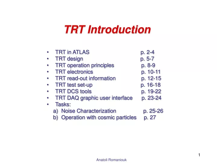
TRT Introduction TRT in ATLAS p . 2-4 TRT design p . 5-7 TRT operation principles p . 8-9 TRT electronics p . 10-11 TRT read-out information p . 12-15

E N D
TRT Introduction • TRT in ATLAS p. 2-4 • TRT design p. 5-7 • TRT operation principles p. 8-9 • TRT electronics p. 10-11 • TRT read-out information p. 12-15 • TRT test set-up p. 16-18 • TRT DCS tools p. 19-22 • TRT DAQ graphic user interface p. 23-24 • Tasks: • Noise Characterization p. 25-26 • Operation with cosmic particles p. 27
Introduction: TRT concept Radiator Straws Radiator Straws
Straw - the main detector element Straw design Straw cathode – 4mm TR optimization: the larger diameter the better Wire offset ~300 mm: the larger diameter the better Self limited streamer length ~1 mm the larger diameter the better Max electron drift-time the smaller diameter the better Straw wall Reinforced straw In order to make straw rigid 4 C-fibres are attached along the straw Wire diameter – 30 mm Max electron drift-time the larger diameter the better Operation stability the smaller diameter the better
TRT design:End-Cap Plane wheel Electronics Electronics cooling pipes Straw connection in the End-Cap TRT Active web C-fibre Ring 3 Outer gas manifold C-fibre Ring 2 HV contacts to the straw inner surface Straws and radiators One 8-plane wheel: 2 x 4 x 768 = 6144 straws End-Cap: 40 x 8-plane wheels C-fibre Ring 1 Inner gas manifold
TRT design: Barrel Wire fixation pin Front end electronics Outer gas manifold Gas manifold Fibre radiator Straws 52544 straws Wire split in two parts at the middle
Transition radiation detectors: principle Radiator. Photon irradiation probability ~ 1/a (1/137) e2 • Requirements: • Maximum e1/e2 • Minimum Z • L1 & L2 compatible with the formation zones in corresponding media e1 L2 L1
Choice of the thresholds 6 keV 300 eV High level threshold Low level threshold Electrons with radiator At 5.7 keV thr. Pe~0.3 Pp=0.05 The less threshold the betterdrift-time accuracy and efficiency The higher threshold the less noise Noise Signal Electrons without radiator
Tracking 25 ns 25 ns 25 ns Leading edge distribution Tailing edge distribution For low level discriminator bit status each 3.125 ns
Test set-up TRT Barrel module TRT Barrel modules TRT End-Cap wheel TRT Barrel modules equipped for the readout TRT Barrel modules assembles in the support structure 16
Service racks TRT Envelope ventilation HV system rack Active gas rack Front-End electronics Cooling Rack
Straw-electronics connectivity End-Cap Wheel prototype: Front-End Electronics connections End-Cap Wheel prototype: Straw-electronics connectivity
Tasks1: Noise characterization • Sources of the noise • Thermal noise • External pick up noise • Internal pick up noise • Dependence on threshold • The less threshold • the better accuracy • the larger noise • Particle loses ~ 1 keV in Ar-mixture • One primary ionization cluster ~ 80-100 eV (3-4 el) • Electronics noise with the detector ~3000 el • Nominal threshold should be >4 sigma above the noise (now ~14000 el) • Phys. Threshold = El.Thr* W/(Gas gain * Signal fraction) • In our case ~14000 el*27/5*104*0.12 = 63 eV • We are sensitive to a 1 primary ionization cluster! • Threshold are set in DAC counts • 10 DAC counts =~1400el or 6.3 eV
Tasks1: Noise characterization • Identify problematic channels and choose the operating threshold. • Misbehaving channels • Requirements • Analysis noise maps at different thresholds • Dead channels • Readout problem • Large noise • Too high or too low thresholds • Methods of the noise source identification and noise signal suppression • Signal shape. • Time distribution. • Noise rate estimate. • Operating threshold • What noise occupancy is allowed to be? • Noise scan • Analysis Tool: TRTVeiwer (see test manual)
Task 2:Operation with cosmic particles • Identify detector problems, straw efficiency, tracking accuracy as a function of the electronics threshold • Signal from particles • Signal shape • Drift-time distribution (hit arrival time, trailing edge) • Method of timing of the signals from particles • Cosmic particle track characterization. • Misbehaving channels • Dead • HV problems • Straw mapping with particles • Straw efficiency and drift-time accuracy • Straw efficiency as a function of threshold • Drift-time accuracy as a function of threshold • Tracking at high occupancy and noise suppression • Basic principles of the particle Identification • Compare HL threshold distributions at different conditions • Choice of the correct representation of the results • Analysis Tool: TRTVeiwer (see test manual)