Download
1 / 47
470 likes | 490 Vues
Learn how to integrate your custom IP with the OPB bus, import peripherals using the wizard, and understand the limitations involved.

E N D
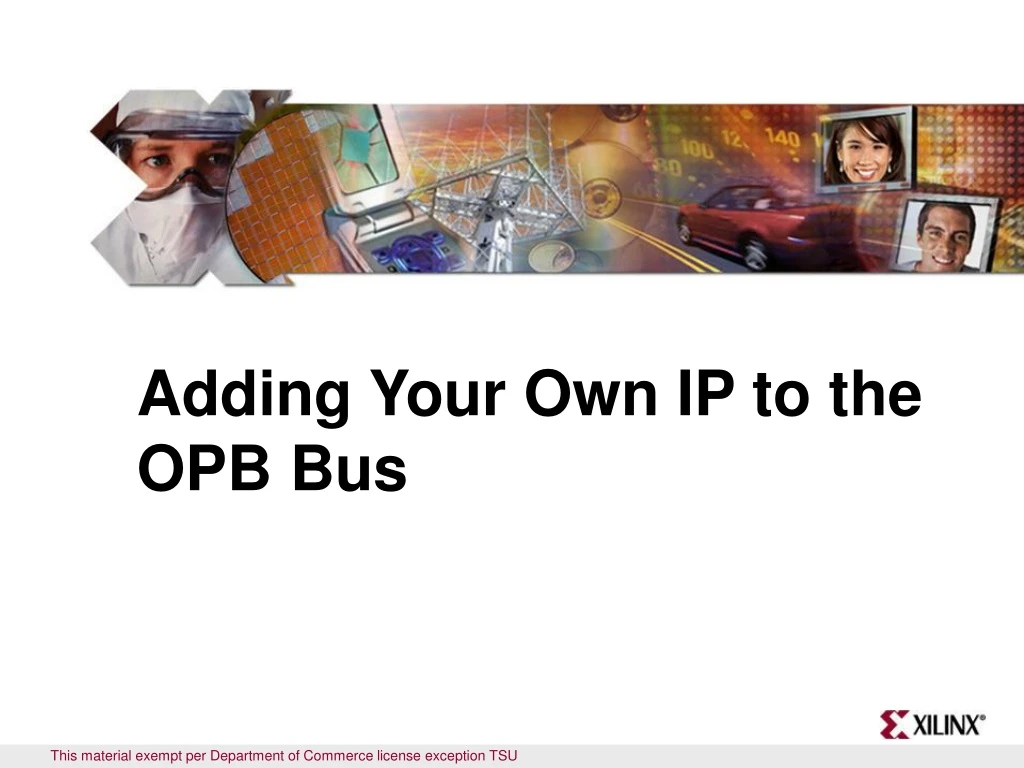
Adding Your Own IP to the OPB Bus This material exempt per Department of Commerce license exception TSU
Objectives After completing this module, you will be able to: • Understand basic OPB bus transactions • Differentiate between free and evaluation-based IP delivered in EDK • Identify the requirements for integrating your IP • List the steps involved in importing peripherals when using the wizard • Identify the limitations of creating peripherals with the wizard
Outline • OPB Bus • XPS Directory Structure • File Creation: MPD, PAO, BBD • IP Delivery in EDK • Creating/Importing Peripheral Wizard
Overview • The peripherals are connected to the microprocessor by using the data and address buses • Xilinx has implemented IBM's CoreConnect bus architecture • On-chip Peripheral Bus (OPB) version 2.1 of the CoreConnect architecture is designed for easy connection of on-chip peripheral devices • Any custom peripheral that connects to the OPB bus must do the following: • Meet the principles of the OPB protocol • Meet the requirements of the Platform Generator • This allows you to take advantage of the simple automated flow that generates the system-level architecture
Features • Platform Generator supports the following features for OPB peripherals, and it is a subset of the OPB v2.1 features • Fully synchronous single-clock edge • 32-bit address bus, 32-bit data bus • Single-cycle transfer of data between the OPB master and the OPB slave • Supports master byte enables • Supports slave timeout suppress • Supports slave retry • No three-state drivers required • Note that the dynamic bus sizing feature is not supported in OPB v2.1
Features • IBM PowerPC embedded system
Physical Implementation • The OPB bus architecture (v2.1) allows for the addition of peripherals to the system, without changing the existing I/O on either the OPB arbiter or the other existing peripherals
<Sln>_xferAck <Sln>_errAck <Sln>_toutSup <Sln>_retry <Sln>_DBus OPB Bus Logic OPB Slave OPB_select OPB_RNW OPB_BE OPB_seqAddr OPB_ABus OPB_DBus Interface Signals • Global OPB slave signals • Slave signals • <Sln>_xferAck • <Sln>_errAck • <Sln>_toutSup • <Sln>_retry • <Sln>_DBus • OPB bus signals • OPB_select • OPB_RNW • OPB_BE • OPB_seqAddr • OPB_Abus • OPB_DBus
1 2 3 4 5 6 Cycles OPB_CLK OPB_select Valid Address OPB_ABus Read OPB_RNW Valid BE OPB_BE 0000-0000 0000-0000 Valid Data <Sln>_DBus <Sln>_xferAck Timing Diagram (Read) • The OPB master asserts OPB_select, then puts valid OPB_ABus, OPB_BE, and OPB_RNW on the buses • The slave completes the transfer by asserting OPB_xferAck, which causes the master to latch data from the data bus on read transfers and de-assert OPB_select
1 2 3 4 5 6 Cycles OPB_CLK OPB_select Valid Address OPB_ABus Write OPB_RNW Valid BE OPB_BE Valid Data OPB_DBus <Sln>_xferAck Timing Diagram (Write) • The OPB master asserts OPB_select, then puts valid OPB_ABus, OPB_BE, OPB_RNW, and OPB_DBus on the buses • The slave latches the data, then completes the transfer by asserting OPB_xferAck, which causes the master to de-assert OPB_select 0000-0000 0000-0000
Outline • OPB Bus • XPS Directory Structure • File Creation: MPD, PAO, BBD • IP Delivery in EDK • Creating/Importing Peripheral Wizard
EDK Tool Flow Simulation Generator Library Generation Hardware Platform Generation CompEDKLib CompXLib MSS MHS TestbenchStimulus IP Models ISE Models IP Library or User Repository SimGen EDK SWLibraries Drivers,MDD LibGen MPD, PAO PlatGen .a PCoreHDL System andWrapper VHD BehavioralVHD Model system.BMM ISETools Synthesis (XST) Embedded Software Development NGC ApplicationSource.c, .h, .s SimGen UCF NGDBuild NGD Compiler (GCC) StructuralVHD Model MAP .o NCD, PCF Linker (GCC) PAR NCD system.BIT BitGen SimGen system_BD.BMM ELF BitInit TimingVHD Model download.BIT Simulation download.CMD iMPACT
Project Directory MyProcessorIPLib pcores pcores <ip_name> <ip_name> data simmodels hdl netlist verilog vhdl MPD PAO BBD XPS Directory Structure • Platform Generator searches the following directories for IP: • pcores directory (located in theproject directory) • MyProcessorIPLib directory(user defined) • Repository Directory listed usingProjectProject OptionsDevice and Repository tab • $XILINX_EDK/EDK/hw/XilinxProcessorIPLib/pcores (UNIX) • %XILINX_EDK%\EDK\hw\XilinxProcessorIPLib\pcores (PC)
Outline • OPB Bus • OPB User Core Templates • XPS Directory Structure • File Creation:MPD, PAO, BBD • IP Delivery in EDK • Creating/Importing Peripheral Wizard
EDK Tool Flow Simulation Generator Library Generation Hardware Platform Generation CompEDKLib CompXLib MSS MHS TestbenchStimulus IP Models ISE Models IP Library or User Repository SimGen EDK SWLibraries Drivers,MDD LibGen MPD, PAO PlatGen .a PCoreHDL System andWrapper VHD BehavioralVHD Model system.BMM ISETools Synthesis (XST) Embedded Software Development NGC ApplicationSource.c, .h, .s SimGen UCF NGDBuild NGD Compiler (GCC) StructuralVHD Model MAP .o NCD, PCF Linker (GCC) PAR NCD system.BIT BitGen SimGen system_BD.BMM ELF BitInit TimingVHD Model download.BIT Simulation download.CMD iMPACT
Parameters override generics in VHDL MPD File ## MPD file created automatically for design OPB_SEMAPHORE BEGIN opb_pwm, IPTYPE=PERIPHERAL ## Parameter list for the generics PARAMETER C_OPB_AWIDTH = 32, DT = integer PARAMETER C_OPB_DWIDTH = 32, DT = integer PARAMETER C_BASEADDR = 0xFFFF8000, DT = std_logic_vector PARAMETER C_HIGHADDR = 0xFFFF80FF, DT = std_logic_vector PARAMETER C_NO_CHANNELS = 4, DT = integer PARAMETER C_MAX_RESOLUTION = 16, DT = integer OPTION SIM_MODELS = BEHAVIORAL : STRUCTURAL BUS_INTERFACE BUS=SOPB, BUS_STD=OPB, BUS_TYPE=SLAVE entity OPB_PWM is generic ( C_OPB_AWIDTH : integer := 32; C_OPB_DWIDTH : integer := 32; C_BASEADDR : std_logic_vector(0 to 31) := X"FFFFA000"; C_HIGHADDR : std_logic_vector := X"FFFFA0FF"; C_NO_CHANNELS : integer range 0 to 15 := 4; C_MAX_RESOLUTION : integer range 4 to 32 := 16 );
## Port list for the signals ## Global signals PORT OPB_Clk = "", DIR = in, SIGIS=CLK, BUS=SOPB PORT OPB_Rst = OPB_Rst, DIR = in, BUS=SOPB ## OPB signals PORT OPB_ABus = OPB_ABus, DIR = in, VEC = [0:31], BUS=SOPB PORT OPB_BE = OPB_BE, DIR = in, VEC = [0:3], BUS=SOPB PORT OPB_RNW = OPB_RNW, DIR = in, BUS=SOPB PORT OPB_select = OPB_select, DIR = in, BUS=SOPB PORT OPB_seqAddr = OPB_seqAddr, DIR = in, BUS=SOPB PORT OPB_DBus = OPB_DBus, DIR = in, VEC = [0:31], BUS=SOPB PORT PWM_DBus = Sl_DBus, DIR = out, VEC = [0:31], BUS=SOPB PORT PWM_errAck = Sl_errAck, DIR = out, BUS=SOPB PORT PWM_retry = Sl_retry, DIR = out, BUS=SOPB PORT PWM_toutSup = Sl_toutSup, DIR = out, BUS=SOPB PORT PWM_xferAck = Sl_xferAck, DIR = out, BUS=SOPB PORT PWM = "", DIR = out, VEC = [0:C_NO_CHANNELS-1] END OPB Bus Signals Slave Signals MPD File port ( -- Global signals OPB_Clk : in std_logic; OPB_Rst : in std_logic; -- OPB signals OPB_ABus : in std_logic_vector(0 to 31); OPB_BE : in std_logic_vector(0 to 3); OPB_RNW : in std_logic; OPB_select : in std_logic; OPB_seqAddr : in std_logic; OPB_DBus : in std_logic_vector(0 to 31); PWM_DBus : out std_logic_vector(0 to 31); PWM_errAck : out std_logic; PWM_retry : out std_logic; PWM_toutSup : out std_logic; PWM_xferAck : out std_logic; PWM : out std_logic_vector(0 to C_NO_CHANNELS-1) );
PAO File ############################################################# # opb_core_ssp0 pao file ############################################################# lib proc_common_v1_00_b proc_common_pkg lib proc_common_v1_00_b pselect lib proc_common_v1_00_b or_muxcy lib ipif_common_v1_00_a ipif_pkg lib ipif_common_v1_00_a ipif_steer lib opb_bus_attach_v1_00_a reset_mir lib opb_bus_attach_v1_00_a opb_bus_attach lib opb_ipif_ssp0_v1_00_a opb_ipif_ssp0 # --USER-- add all user core source files and change the following source to # your top level core name and library lib opb_core_ssp0_v1_00_a pwm lib opb_core_ssp0_v1_00_a user_logic lib opb_core_ssp0_v1_00_a opb_core_ssp0 Order of dependency Update this section
BBD File • The Black Box Definition (BBD) file identifies files used for a user peripheral • The NGC netlists are copied into the project/implementation directory • Example of a single file without options • FILES • Blackbox.ngc • Example of multiple file selections without options • FILES • blackbox1.ngc, blackbox2.ngc, blackbox3.edn
File Usage • There are two ways to integrate your own IP into XPS • As a blackbox • Synthesized with XST or a third-party synthesis tool • Requires MPD and BBD • As HDL • Synthesized with the rest of the processor system • Uses XST • Requires MPD and PAO
Outline • OPB Bus • OPB User Core Templates • XPS Directory Structure • File Creation: MPD, PAO, BBD • IP Delivery in EDK • Creating/Importing Peripheral Wizard
IP Peripherals • Xilinx has created a wide variety of IP cores: • Bus infrastructure cores • PLB2OPB bridge • PLB • Memory interface cores • PLB block RAM • PLB Double Data Rate (DDR) Synchronous DRAM (SDRAM) controller • Peripherals • OPB Serial Peripheral Interface (SPI) • Ethernet Media Access Controller (EMAC) • User core template • OPB slave attachment • OPB master attachment
OPB UART-16550 OPB HDLC OPB IIC OPB Ethernet 10/100 MAC and Ethernet-Lite 10/100 MAC OPB ATM Master Utopia Level 2 OPB ATM Slave Utopia Level 2 OPB PCI 32 Bridge OPB ATM Master Utopia Level 3 OPB ATM Slave Utopia Level 3 PLB ATM Master Utopia Level 2 PLB ATM Slave Utopia Level 2 PLB Ethernet PLB RapidIO Xilinx developed, delivered, and supported IP Cores Included as Evaluation The Evaluation IP installs with a 90-day evaluation license
Core Sizes • The size of each core is available in the data sheet • For example, the opb_ethernetlite_v1_01_b data sheet contains the following table:
Processor System Size • The Processor IP Calculator is an online tool that helps you easily estimate the processor IP core size usage • www.support.xilinx.com/ipcenter/processor_central/ppcip/calc.htm • Try it out!!
Outline • OPB Bus • OPB User Core Templates • XPS Directory Structure • File Creation: MPD, PAO, BBD • IP Delivery in EDK • Create/Import Peripheral Wizard
Create/Import Peripheral Wizard • The wizard helps you create your own peripheral and then import it into your design • The wizard will generate the necessary core description files into the user selected directory • You can start the wizard after creating a new project or opening an existing project in XPS • The user peripheral can be imported directly through the wizard by skipping the creation option • Ensure that the peripheral complies with Xilinx implementation of the IBM CoreConnect Bus Standard
Starting the IP Wizard The Create and Import Peripheral Wizard can be started after creating a project and using Hardware Create or Import Peripheral … or opening an existing project or using Start Programs Xilinx Platform Studio 8.2i Accessories Create and Import Peripheral Wizard
1 2 Select the target directory – project directory or user repository Select Create Peripheral flow Creating a Peripheral The project directory assigned as the target directory will allow the peripheral to be available to the project without importing it. User repository will allow multiple projects to access the same peripheral by importing it in a project
Selecting a Peripheral Name and Bus 3 4 Provide the peripheral name and version Select the bus to which the peripheral will attach
Selecting Various Functionalities 5 6 Select the number of interrupts if the interrupt mechanism is selected Select the functionality
Creating a PeripheralSelecting S/W Registers and Address Ranges 8 7 Select the number of address ranges and their widths if the option is selected Select the number of S/W registers and their widths if the option is selected
Selecting Additional Signals and ISE Project Generation 9 10 Select the additional signals if the peripheral requires it Optional Bus Functional Model Simulation template
Selecting Additional Signals and ISE Project Generation 11 12 Optional Implementation Tools support Finish Since the project directory was assigned as the target directory the peripheral will appear in the IP Catalog under Project Repository folder
1 2 Select Import Peripheral flow Identify the Repository Directory Importing a Peripheral
4 3 Select HDL Source files Enter the top entity name and version name • The name of the peripheral must match the top-level entity name or module name • The user version name is optional • Source file types can be a combination of HDL sources, netlists, and documentation files • The top-level HDL must conform to the CoreConnect bus architecture standard Custom IP Name and Source
5 6 Select language and browse to source files Select HDL source files and libraries • The HDL language can be VHDL or Verilog • Source files can already be in a project • Source files can be browsed • Select the libraries and source files in order of dependency, from lowest to highest Custom IP HDL and Location
8 7 Verify that all ports are connected properly Select bus interface • If CoreConnect bus architecture naming conventions are followed, the ports are matched; if not, you must assign them Bus Interface
10 9 Select source and any type of interrupt Verify the bus information • Select interrupting signal source, type (level versus edge), and polarity • This will be presented only if interrupt present Interrupt Source
12 11 Select port attributes and change the values Select parameter attributes and change the values • The parameters are listed • View or change the parameter default values • The changed value is reflected in the MPD file • The ports area is listed • View or change the parameter default values • The changed value is reflected in the MPD file Attributes
Generating Custom IP • If the netlist and documentation files were selected earlier, the corresponding GUI displays, requesting their locations • If not, the Finished GUI displays • If the save box is checked, the previously generated files will also be saved The peripheral will appear under the Peripheral or Project Repository folder in the IP Catalog
Review Questions • What is the process for creating a peripheral of custom IP in XPS? • What is the process for importing a piece of custom IP into XPS? • If you are using a third-party synthesis tool to compile your IP, what files are required to integrate that IP into XPS?
Answers • What is the process for creating a peripheral of custom IP in XPS? • Start the Create and Import Wizard tool from XPS • Select the Create templates for a new peripheral option • Identify the destination directory location • Select the bus interface • Select functionality and any interrupts • Define any software registers and address ranges • Add additional signals which the peripheral may be using • Generate the files • Add user logic in user_logic.vhd
Answers • What is the process for incorporating a piece of custom IP into XPS • Develop your custom IP by using any combination of HDL, netlist, or libraries • Make sure that the top-level file conforms to CoreConnect requirements • Start the Importing IP Wizard tool from XPS • Identify location of libraries, netlists, and source files in the order of dependency • Select the bus interface • Select the source and type of the interrupt, if any • If you are using a third-party synthesis tool to compile your IP, what files are required to integrate that IP into XPS? • MPD and BBD
Where Can I Learn More? • Tool documentation • Platform Specification Format Reference Manual • Processor IP Reference Guide • Embedded System Tools Guide Create/Import Peripheral Wizard • Embedded System Tools Guide Microprocessor Peripheral Description • Embedded System Tools Guide Peripheral Analyze Order • Xilinx Drivers • Support website • EDK Home Page: support.xilinx.com/edk