Download
1 / 19
190 likes | 343 Vues
Explore the significance of valve designs in improving breathing abilities for internal combustion engines. Discover the various types of valves like poppet, rotary, reed, and piston-controlled porting valves along with their locations. Learn about different valve arrangements such as T-head, L-head, F-head, I-head, and the operating mechanisms associated with each. Discover the geometric nomenclature for valves and the stages of valve lifting. Dive into the intricacies of single and double overhead camshaft configurations, ideal gas equations for intake processes, and more. Enhance your knowledge on crucial hardware for optimal engine performance.

E N D
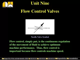
Flow through Valves P M V Subbarao Professor Mechanical Engineering Department Breathing abilities are limited by Smallest Areas of Flow ….
A I R FUEL A I R First Law Analysis: USUF SI Engine CI Engine Intake Process:
SI Engine CI Engine
Ideal Gas Equation for Intake Process Instantaneous EoS: Instantaneous Mass Flow Rate:
Options for Most Important Hardware for Better Breathing Valve/Port Design 1. Poppet Valve 2. Rotary Valve 3. Reed Valve 4. Piston Controlled Porting Valve Location 1. The T-head 2. The L-head 3. The F-head 4. The I-head: (i) Over head Valve (OHV) (ii) Over head Cam (OHC)
Arrangement of Poppet Valves • The majority of internal combustion engines also are classified according to the arrangement of the intake and exhaust valves, whether the valves are located in the cylinder head or cylinder block. • L-HEAD —The intake and the exhaust valves are both located on the same side of the piston and cylinder. • The valve operating mechanism is located directly below the valves, and one camshaft actuates both the intake and the exhaust valves
I-HEAD —The intake and the exhaust valves are both mounted in a cylinder head directly above the cylinder. • This arrangement requires a tappet, a pushrod, and a rocker arm above the cylinder to reverse the direction of valve movement. • Although this configuration is the most popular for current gasoline and diesel engines. • It was rapidly superseded by the overhead camshaft.
F-HEAD: • The intake valves are normally located in the head, while the exhaust valves are located in the engine block. • The intake valves in the head are actuated from the camshaft through tappets, pushrods, and rocker arms. • The exhaust valves are actuated directly by tappets on the camshaft.
T-HEAD —The intake and the exhaust valves are located on opposite sides of the cylinder in the engine block, each requires their own camshaft.
SINGLE OVERHEAD CAMSHAFT • The camshaft is located in the cylinder head. • The intake and the exhaust valves are both operated from a common camshaft. • The valve train may be arranged to operate directly through the lifters, as shown in view A, or by rocker arms, as shown in view B. • This configuration is becoming popular for passenger car gasoline engines.
DOUBLE OVERHEAD CAMSHAFT • When the double overhead camshaft is used, the intake and the exhaust valves each operate from separate camshafts directly through the lifters. • It provides excellent engine performance and is used in more expensive automotive applications.
Geometrical Nomenclature for Valves • The instantaneous valve flow area depends on valve lift and the geometrical details of the valve head, seat and stem. • There are three separate stages to the flow area development as valve lift increases.