Download
1 / 28
290 likes | 484 Vues
Learn the importance of flow control valves and needle valve symbols in achieving optimal performance for hydraulic circuits. Understand the role of needle valves, orifices, pressure differentials, and how they impact actuator speed and fluid flow.

E N D
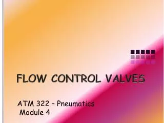
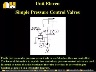
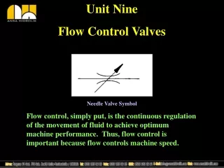
Unit Nine Flow Control Valves Needle Valve Symbol Flow control, simply put, is the continuous regulation of the movement of fluid to achieve optimum machine performance. Thus, flow control is important because flow controls machine speed.
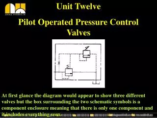
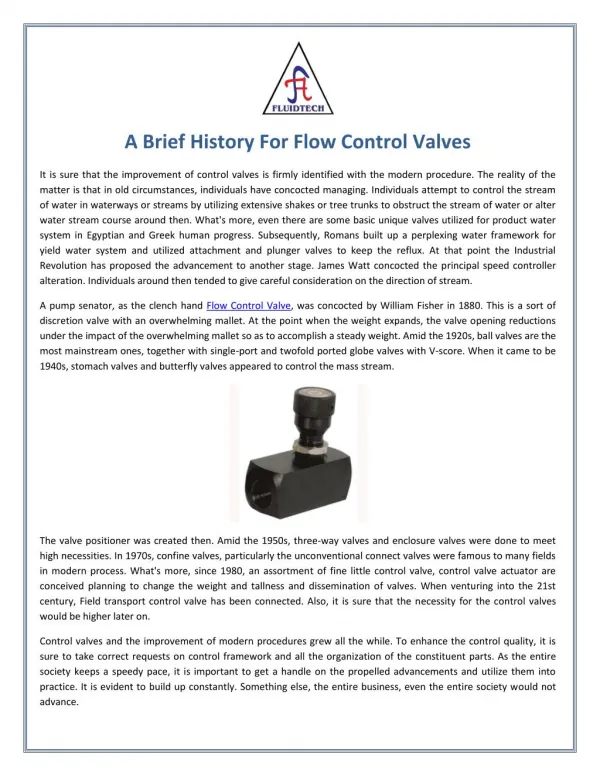
Flow Control in General It would be prudent at this point to mention the fact that when discussing flow control two different meanings exist. First, one has the “topic” of flow control involving the various devices that perform this task. Second, there is the industry tendency to refer to a particular device as a “flow control.” The latter is a nickname for a control valve that has, as a integral part of its design, a needle valve and check valve together in the same body or as a unit.
Control of Flow You should identify the above circuit as “hydraulic.” The primary influence for flow is the pump. With the relief valve set at 500psi and no resisting load on the actuator, the rod extends at full speed. Often in industrial fluid power systems we do not allow actuators to extend at full speed because of the risk of damage to the machine, work piece, or operator.
Control of Flow With a needle valve placed in series between the directional control valve and the actuator, fluid is resisted causing some of the pump flow to go over the relief valve. The diversion of flow slows down the actuator. Remember that fluids take the path of least resistance.
Orifice An orifice is no more than a tiny opening, placed in the path of fluid to restrict it. It could be a precision machined piece or simply a pipe plug with a hole in it. Whatever it may be it is not adjustable. The size of the opening, the pressure on the fluid in front of the opening, and temperature, if its oil, all affect the flow across the orifice.
Variable Orifice The above term simply means that you can adjust the flow control device. Technically, any of the devices above could be used as a flow control but only one design is desirable because of its low restriction and that would be the needle valve. Examine the needle valve symbol back in the frame that showed the circuit. The addition of the arrow determines it to be adjustable.
Orifice in a Circuit In the circuit above, the orifice allows only 2gpm to pass at 500psi. This in turn forces the other 3gpm to go back to tank. Since actuator speed is controlled by flow, the speed of the actuator is limited to the supplied 2gpm instead of the full 5gpm. (See next slide for explanation.)
Calculating Cylinder Speed In the previous example, the formula used to calculate the speed of the cylinder was Rod Speed(feet per minute) = GPM x 19.25/ Piston Area. If you do the math, it will NOT come out correctly as there is a mistake in the text. Your answer should have been 12.8fps. Try again but this time use the following formula: Rod Speed(in/min) = GPM x 231 Piston Area(in squared inches) This time your answer should be 154 inches per minute. Divide by 12 to get feet per minute. Sorry but text books are like people, none are perfect.
Orifice Size Increased or Decreased The rod speed formula illustrates mathematically the relationship between flow and actuator speed. By adjusting the size of the orifice speed can be altered. Increasing orifice size allows more flow which increases speed. Decreasing orifice size decreases flow which in turn decreases speed.
Pressure Differential affects Flow If pressure on the fluid were to increase directly in front of the orifice, fluid flow across the orifice would increase and so would actuator speed. In fact, when ever fluid is moving across a restriction of any type, there will be a difference of pressure.
Pressure Differential Pressure differential is the difference in pressure between any two points in a fluid power system. It is sometimes referred to as “Delta P.”
Examples from Everyday Life The illustrations compare two fluids. The toothpaste represents a liquid and the air mattress a gas. In both cases the fluid is aided in its movement when a force is applied increasing the pressure within.
Needle Valves “Cause” Pressure Differential In the text it refers to needle valves as being “affected” by pressure differential when in fact it is the needle valve that causes the change due to its resistance. The precise nature of adjustment allows us to determine what that change will be under certain circumstances. As for return oil, what ever does not go out into the system will have to go back to tank.
Relief Valve Setting affects Flow across a Needle Valve This illustration demonstrates that if you increase pressure in front of an orifice(needle valve), the flow through the orifice will increase. Recall that one of the three things that affects flow across any restriction is the pressure applied to it.
Affect of Work Load on Pressure. Since the load is resistance it should follow that any increase in load will likewise have an affect on pressure. Simply put, an increase in load results in a proportional increase in pressure. Pressure generated is always the amount required to overcome the load, nothing more. In addition, if the load increases to a point above relief valve setting, the actuator will stall out.
Pressure Compensated Flow Control Valve To help neutralize the effects of upstream and downstream pressure changes, a valve capable of changing its flow is used. Note the addition of a straight arrow pointing up shown in the schematic symbol as indicated by the red arrow.
Restrictor type P.C. Flow Control The restrictor type P.C. Flow Control is the most type used in industry. It has the addition of a spool valve which is spring offset to the full flow position. As pressure builds from resistance the spool moves against the spring and cuts down flow based on the pressure differential across its ports. The adjustment is the same as a non-compensated flow control.
P.C. Flow Control in a Circuit The purpose of the P.C. flow control here is to keep the cylinder moving at a constant rate of speed even if the load changes. Certain operations can not tolerate uncontrolled movement. It should be noted that P.C. flow controls are used only in hydraulics.
Increase of Work Load or Relief Valve Pressure The compensator spring has a value of 100psi in order to develop flow. This should be considered if the load increases because you must have at least a 100psi differential between the relief valve setting and the work load in order to develop enough flow to move the load.
Temperature Affects Flow As a liquid takes on heat it gets thinner. The result of thinned oil is lessened viscosity and this results in increased flow. As you know, increased flow means increased actuator speed. So when machines warm up, their operating characteristics will change.
Temperature Compensation The idea behind the metal rod is that metal expands when heated. When the rod expands it extends directly in the path of fluid flow, reducing in direct proportion to temperature.
Sharp Edge Orifice The operating principles of this device are not clearly understood but its effect is very precise control of flow. This design is very common although tricky to manufacture.
Temperature-Pressure Compensated Flow Control Valve A temperature-pressure compensated flow control should be used wherever there exists extreme temperature differentials between start up and operating temperatures.
Meter-In Flow Control In the circuit above, a positive load resting on the cylinder rod makes meter-in an acceptable choice for flow control because nothing can “pull” on the rod. Another example is the old style in-ground car lifts that were used in garages years ago. The weight of the vehicle was the positive load and gravity ensured that there would be no “runaway.”
Meter-Out Flow Control Where a load is pulling on a cylinder rod some means is needed to prevent the piston from out running the oil supply as in the case of a runaway load. The technique is simply to use the incompressible nature of oil to hold back the rod at the rate of flow the needle valve is set for. This type of metering is also common in pneumatic systems.
Bleed-Off(by-pass) Flow Control A bleed-off circuit simply works by allowing a portion of the pump’s flow to go back to tank before it gets to the actuator. The general idea is that “leaking” oil back to the tank is better than “forcing” it over the relief valve and generating unnecessary heat. The bleed-off circuit is only good on positive loads or one where precise speed control is not very important.
Reverse Flow As stated in an earlier unit, the primary use of a check valve is by-pass. In the above circuit, the check valve allows the oil to go around the flow control so that it only meters in one direction. Check valves are also used on pressure controls.
Pneumatic Control of Flow Although the pressure regulator is classified as a pressure control valve, it also affects flow by throttling air movement. As pressure builds at the outlet, the regulator begins to shut off until its setting has been reached where it is closed. Between full open and full close the regulator limits air movement based on its opening.