CONTROL VALVES
CONTROL VALVES. By M.Freethan M-42801. FACTS AND ILLUSIONS Introduction Control valves Types of control valves Actuators Positioners Case study on handling control valves smartly. What are VALVES? Mechanical devices designed to direct, stop, mix

CONTROL VALVES
E N D
Presentation Transcript
CONTROL VALVES By M.Freethan M-42801
FACTS AND ILLUSIONS • Introduction • Control valves • Types of control valves • Actuators • Positioners • Case study on handling control valves • smartly
What are VALVES? Mechanical devices designed to direct, stop, mix or regulate the flow, pressure or temperature of a process fluid. Kinds of VALVES: On-off valves, One way valves & Throttling valves. Types of VALVES: Gate, Plug, Ball, Butterfly, Check, Pressure-relief & Globe valves.
What are VALVES made of ? Steel, Iron, Plastic, Brass or any other Special Alloys. How to select VALVES ? VALVE Coefficient (Cv): Measurement commonly applied to valves is the valve coeff or the flow coeff. If Cv is not calculated, the valve experiences diminished performance.
Too small Cv : • Valve under sized • Starving for fluid • Buildup of upstream pressure • Higher backstream pressure damaging equipments • Cavitation & Flashing • Too large Cv : • Large oversized valve is selected • Cost, size & weight increases • Higher pressure drops and faster velocity causing • cavitation, flashing & corrosion • Bath tub stopper effect
Cv is defined as number of US gallons per minute of water at 60°F that flows through valve with a pressure drop of 1 Psi
How do we compare VALVES ? • Rangeability: • Ratio of maximum to minimum flow that can be acted • upon by the VALVE after receiving the signal from • the controller. • Factors affecting rangeability : • Valve’s geometry (plug and seat of a gate valve) • Seat leakage (valve instability) • Actuator (more stiffness at near closure)
Sensitivity : Change in output / Change in input SHUT OFF Classification: ANSI Class I – Open classification-tests not Required, Allows specified agreement over required leakage ANSI Class II – Shutoff is 0.5% of the rated valve Capacity
ANSI Class III – 0.1% rated valve capacity used at places where higher cutoff is required ANSI Class IV – Industry standard for single seated Valve with metal-metal seating surface, 0.01% of rated valve capacity ANSI Class V & VI - Throttling valves where Shutoff is primary
ANSI Class V – Shutoff focus is defined as 0.0005cm²/min per inch of orifice dia/psi Differential used when control valve has to be closed for a long time ANSI Class VI – bubble tight shutoff valve, metal to elastometer soft seating surfaces-independent of pressure differentials
BODY END CONNECTION • Designed to match piping connection, • > 2 inches use thread connection • < 2 inches > flanged • WELDED END CONNECTION - Delivers zero • leakage • Stockweld – HP,HT fluids in < 2in • Buttweld – HT, HP
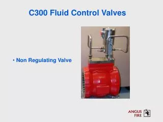
CONTROL VALVE A throttling valve designed with an actuating system to work within control loops. Control valves are throttling valves but all throttling Valves are not control valves
Control valves Body assembly Actuator (Subassemblies) Globe Butterfly Ball Eccentric (Construction)
Air To Close Valve Δ P FLOW =P1-P2 Δ P SHUTOFF =P1-PLOAD 1. USUALLY Δ P SHUTOFF > Δ P FLOW 2. Methods to increase Δ P SHUTOFF 1. Increase PLOAD 2. Increase ADiaphragm 3. Reduce FSpring 4. Reduce ζ Packing ΣFup = ΣFdown P1 * APort+ FSpring+ ζPacking=PLOAD* ADiaphragm+ P2 * APlug Note: Inlet Pressure tends to push open plug
Air To Open Valve Δ P FLOW =P1-P2 Δ P SHUTOFF =P1-PLOAD 1. USUALLY Δ P SHUTOFF > Δ P FLOW 2. Methods to increase Δ P SHUTOFF 1. Decrease PLOAD 2. Increase ADiaphragm 3. Increase FSpring 4. Reduce ζ Packing ΣFup = ΣFdown P1 * APort+PLOAD* ADiaphragm + ζPacking= FSpring+P2 * APlug Note: Inlet Pressure tends to push open plug
GLOBE VALVES Most common, Rising stem control valves Design simplicity, versatility of applications, easy Maintenance & ability to handle a wide temperature and pressure range Size < 0.5-42 inches >
Globe valves: • Most widely used valve in • Ammonia plant • Has a cage to regulate flow
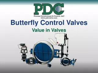
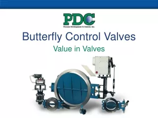
BUTTERFLY VALVES Early 1930’ used as ON-OFF block valves, Now used as throttling valves- High performance Butterfly valves is a quarter turn rotatory motion Valve that uses rotating round disk as a regulating Element. Size< 2 in- 8 in > Cons – deadband Pros – smaller & lighter in weight
Butterfly valves: • Used widely in water • treatment plant since • Large pipes are used
BALL VALVES Similar to butterfly control valves, Accurate Control possible, Improved sealing & highly accurate Matching of balls have provided tight shutoff. Used in slurries or pulp applications. Can be installed vertically in pipe lines.
Ball valves: • Used for slurry • applications
ECCENTRIC VALVES Growing in demand , combines the positive Aspects of Ball, Globe, Butterfly, Rotary valves using An offset plug to swing into a seat to close the valve. Pressure drop < 100 psi > Avoids water hammering effects
ACTUATORS A device mounted on a valve that in response to a Signal, automatically moves the valve to the required position using an outside power source. The addition Of an actuator to a throttling valve is called a CONTROL VALVE
ACTUATORS Pneumatic Electronic motor Electro hydraulic Diaphragm Piston
PNEUMATIC ACTUATORS Air is relatively inexpensive, 90% of the Industries employ these actuators. HYDRAULIC ACTUATORS Exceptional stiffness & high thrust’ are required, Fast stroking speeds. Hydraulic fluid above and below a piston to position the valve.
ELECTROHYDRAULIC ACTUATOR Self contained hydraulic system, electrical Signal feeds to an internal pumps, which uses hydraulic fluid from a reservoir to feed hydraulic fluid above or below the piston. Pros – Exceptionally stiff because of the incompressibility of liquids. Cons – Expensive and Bulky
POSITIONERS A device attached to an actuator that receives An electronic or pneumatic signals from the controller And compares this signal to the actuator’s position.
3-way positioners Send and exhaust air to only one side of a Single acting actuator that is opposed by a range Spring. 4-way positioners Send and exhaust air to both sides of an actuator which is required for double acting actuators.
Reasons To use Positioners • Increase control system resolution • i.e)fine resolution. • Allow use of characteristic cams. • Minimize packing friction effects. • Allow Split Ranging. • Overcome seating friction in rotary valves. • Facilitate operation when the higher number in the bench-set range is greater than 1ksc
Reasons To use Positioners • Permit use of piston actuators. • Allow distance between controller and control valve using the advantage of • 4-20ma signal.
CASE STUDY Implementing FUZZY concepts in controllers driving the control valves
References • Valves handbook • Fuzzy logic by Lofti.A.Zadeh • Valves presentation by • Mr.Charles Dhanraj