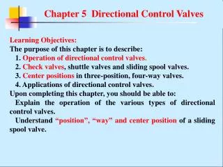
Chapter 6 Pressure Control Valves
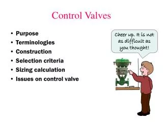
Chapter 6 Pressure Control Valves. Objectives : The purpose of this chapter is to describe: 1 . Operation of pressure control valves . 2. P ressure relief valves, pressure reducing valves, sequence valves, and pressure switches .

Chapter 6 Pressure Control Valves
E N D
Presentation Transcript
Chapter 6 Pressure Control Valves Objectives: The purpose of this chapter is to describe: 1. Operationof pressure control valves. 2. Pressure relief valves, pressure reducing valves, sequence valves, and pressure switches. 3. Measure andcontrol quantities of pressure control valve. 4. Applicationsof pressure control valves. Upon completing this chapter, you should be able to: Explain the operation of the various types of pressure control valves. Identify the graphic symbols used for pressure control valves. Distinguish the different types of pressure control valves.
(a) pressure measure (b) pressure sum measure (c) pressure difference measure Measure methods of some usually used physical quantities
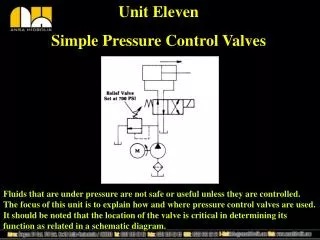
Chapter 6 Pressure Control Valves 6.1 Introduction Pressure control valves are classified as pressure relief valves, pressure reducing valves, sequence valves, and pressure switches. 6.2 Pressure relief valves Pressure relief valves limit/maintain the maximum pressure in a hydraulic circuit by diverting pump flow back to the tank. 6.2.1 Direct-acting pressure relief valve
Chapter 6 Pressure Control Valves 1 Structure 2 Operating process When the hydraulic force is less than the spring force, the poppet remains on its seat and no flow pass through the valve. When the hydraulic force is greater than the spring force, the poppet will be forced off its seat, and fluid will flow back to the tank through port T.
Chapter 6 Pressure Control Valves 3 Equilibrium equation Neglecting the poppet weight, friction force, and flow force, the static force equilibrium equation of the poppet is
Chapter 6 Pressure Control Valves ps----starting pressure; pT----setting or predetermined level; Δp= pT-ps steady overshoot; 4 Characteristic curve attention The relief valve should be able to pass through the overall flow rate of the pump. 5 advantage and disadvantage The direct-acting pressure relief valve has a simple construction and a high sensitivity; however, it is not suitable for the application of high pressure and high flow rate.
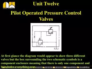
Chapter 6 Pressure Control Valves 6.2.2 Pilot-operated pressure relief valves 1) View and constitution
Chapter 6 Pressure Control Valves 1 Schematic 1-pilot valve; 2-poppet seat; 3-valve cap; 4-valve body; 5-orifice; 6-main spool; 7-main valve seat; 8-main spring; 9-adjustment spring Port P1 is connected to the pump line. Port T is connected to the tank. 2) components
Chapter 6 Pressure Control Valves 3) cuicuit
Chapter 6 Pressure Control Valves If p1 is very small, both close. As soon as p1 reaches the setting, it will force the pilot poppet off its seat. A small amount of flow begins to go through the pilot line and the piston orifice back to tank. (pilot valve opening) 4) Operating process When p1 further rises, the opening of the pilot valve further increases. As a result, the pressure drop of the camping orifice causes the piston to lift off its seat and the flow goes directly from the pressure port to the tank. (both valve opening) Measure and control quantity: inlet pressure
Pilot valve: Chapter 6 Pressure Control Valves 5) Equilibrium equation Neglecting the poppet weight, friction force, and flow force, the static force balance equation of the poppet is if the Kxis very small and x0>>x, thus p2≈Kxx0/A3(constant) main valve: ΣFy= Ky(y0+y) -p1A1+p2A2=0 That is p1=Ky(y0+y)/A1 +p2A2 /A1 if the Kyis very small and y0>>y, thus p1≈Kyy0/A1 + (Kxx0/As) A2 /A1 (constant)
6) Remotely adjusting pressure The pilot relief valve is set for the maximum pressure that the circuit is designed. The remote relief valve is set to a lower pressure dictated by the current operating parameters. When s is energized, the systematic pressure is set by the remote pilot relief valve When s is de-energized, the systematic pressure is set by the pilot relief valve.
Chapter 6 Pressure Control Valves 7) Unloading the pump When the vent port is connected to tank via a solenoid directional control valve, the system will be able to be unloaded. (only the main valve opening) 8) advantage The pilot-operated relief valve usually is smaller than a direct-acting relief valve for the same flow and pressure ratings.
6.3 Pressure reducing valves 1 Function: The pressure reducing valve maintains a reduced pressure level in a branch circuit of a hydraulic system. 2 Components
6.3 Pressure reducing valves 3 Orifaces e: camping oriface(fixed) f: throattle oriface(variable) X: openning
6.3 Pressure reducing valves 4 oil circuits
6.3 Pressure reducing valves 5 Euilibrun equation 6 dynamic regulating
6 Measure quantity and control quantity: outlet pressure Drain manner: external drain Outlet port: to an actuator Problem: how does a pressure relief valve?
Chapter 6 Pressure Control Valves 6.4 Sequence valves Sequence valves cause a hydraulic system to operate in a pressure sequence. They are used to control the order of various actuators of a hydraulic system. As soon as the inlet pressure reaches a preset pressure value, the sequence valve will open and let oil pass to a secondary circuit. Sequence valves have two types—direct-acting and pilot-operated. They can also be classified as internal control and external control types according to where the control pressure is from.
Chapter 6 Pressure Control Valves 6.4.1 Direct-acting sequence valves
Chapter 6 Pressure Control Valves One-way sequence valve and counterbalance valve • One-way internal control sequence valve • One-way external control sequence valve • One-way internal control counterbalance valve • (d) One-way external control counterbalance valve
Chapter 6 Pressure Control Valves 6.6.1 Pressure regulation circuit In a fixed displacement pump system, the supply pressure of a hydraulic pump is regulated by a pressure relief valve. In a variable displacement pump system, a pressure relief valve is used as a safety valve to limit the systematic maximum pressure and prevent a system from overloading. When a system needs more than two pressure levels, a multi-pressure regulation circuit is used. 6.6.1.1 Single stage pressure regulation circuit The supply pressure of pump can be regulated by adjusting the pressure relief valve. The setting pressure of pressure relief valve must be more than the sum of hydraulic cylinder maximum pressure and all pressure losses in the circuit.
Chapter 6 Pressure Control Valves 6.6.1.2 Bi-directional pressure regulation circuit
Chapter 6 Pressure Control Valves 6.6.1.3 Multi-pressure regulation circuit Bi-stage pressure regulation circuit and multi-stage pressure regulation circuit can reduce overflow power loss.
Chapter 6 Pressure Control Valves 6.6.2 Pressure reducing circuit