Download
1 / 31
490 likes | 1.17k Vues
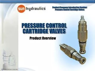
Product Overview. PRESSURE CONTROL CARTRIDGE VALVES. Relief Sequence Reducing Reducing/Relieving. Pressure Controls. Normally closed devices used to limit or regulate pressure Many variations to meet application requirements Available in 2, 3, and 4 port configurations

E N D
Product Overview PRESSURE CONTROLCARTRIDGE VALVES
Relief Sequence Reducing Reducing/Relieving Pressure Controls
Normally closed devices used to limit or regulate pressure Many variations to meet application requirements Available in 2, 3, and 4 port configurations Used to protect pumps or actuators, or maintain constant system pressure All hydraulic systems feature at least one relief valve Pressure Controls - Relief
RP*C, Pilot Operated, Balanced PistonRelief Relief Valve – Technical Overview • Accurate pressure control • Low pressure rise with flow • Smooth and quiet • Moderately fast response time • Viscosity sensitive • Susceptible to silting
RD*A, Direct Acting Relief Differential area design Typically smooth and quiet performance Essentially zero leak (suitable for load holding) Dirt tolerant Very fast response Difficult to adjust under pressure Higher pressure rise with flow Relief Valve – Technical Overview
Advantages Relief Valve Comparison Fast response Low leakage Dirt tolerant Capable of operating over a wide temperature range Low over/undershoot Common flow path with P/O design Port 1 - Inlet Port 2 - Outlet Port 1 - Inlet Port 2 - Outlet 2 2 1 1 Relief Valve – Technical Overview Direct Acting Relief Valves Pilot Operated Relief Valves (Sliding Spool) • Wide pressure range • Low hysteresis • Easier to adjust when operating at high pressures • Low override curve • Screened orifice • Common flow path with direct acting
Disadvantages Relief Valve Comparison Moderate hysteresis levels (not equivalent to P/O versions) Moderate pressure override Multiple spring ranges required to optimize performance Difficult to adjust when operating at high pressures Port 1 - Inlet Port 2 - Outlet Port 1 - Inlet Port 2 - Outlet 2 2 1 1 Relief Valve – Technical Overview Direct Acting Relief Valves Pilot Operated Relief Valves (Sliding Spool) • Higher overshoot/undershoot potential • Internal leakage when closed • Temperature limitation • Contaminant sensitive in dirty systems
RP*S, Pilot Operated, Balanced PoppetRelief Relief Valve – Technical Overview • Combines features of pilot operated and direct acting relief valves • Smooth and quiet pressure regulation • Very low leakage • Dirt tolerant • Adjustable under pressure • Very fast response • Eliminates erosion cavity damage
RBA*, Direct Acting, Pilot Stage Relief Relief Valve – Technical Overview • Remotely controls pressure setting of other pilot operated valves • Capacity limited to pilot flow—should only be used with valves with comparable pilot flows • Fast response
RPGT, Pilot Operated, Balanced Poppet, Soft Relief Relief Valve – Technical Overview • Pilot-operated relief that limits maximum system pressure and also the rate of pressure rise • Adjust screw determines the maximum setting and an initial (threshold) setting • Valve opens at threshold and ramps closed (or to maximum setting) at a constant rate in about 250 ms • Controlled rate of rise results in less dynamic stress in a system and no pressure spikes
Relief Valve – Technical Overview Soft Relief Function
Relief Valve Response Comparison Ultimate Pressure System Designed Maximum Pressure and Ultimate Pressure System Designed Maximum Pressure Threshold Pressure Relief Valve – Technical Overview
Relief Valve – Technical Overview RV*A, Ventable, Pilot Operated, Balanced Piston Relief • Essentially a pilot-operated relief valve with a vent port that connects between the main piston and pilot stage • Vent provides for remote control with other pilot or two-way valves by short circuiting the pilot stage • If port 3 is blocked – valve operates as a standard relief If port 3 is open to tank – main section is wide open • Same general characteristics as a pilot-operated relief valve
RV*D, Ventable, Pilot Operated, Balanced Piston Relief with External Drain Relief Valve – Technical Overview • Same as the RV*A valve except with a separate drain for the pilot stage • Valve is insensitive to back pressure at port 2 • Can be thought of as a ventable sequence valve • Same general characteristics as a pilot-operated relief valve
RQ*B, Pilot Operated, Kick-down Relief Relief Valve – Technical Overview • Act similar to a circuit breaker in an electrical system • When pressure at the inlet reaches the valve setting, valve kicks completely open • Valve remains open as long as pressure at port 1 exceeds pressure at port 2 • To reset valve flow must cease • Same general characteristics as a pilot operated relief valve
Normally closed devices used to control a sequence of actions (similar to a relief valve with separate drain line) Supplies flow to a secondary circuit once the pressure at port 1 exceeds the setting of the valve Can be used as a relief if back pressure is present in system Assures that a priority function is completed before a secondary function begins Insures a part is clamped before machining can begin Insures a clam shell bucket is closed before it can be lifted Pressure Controls - Sequence
SX*A, Direct ActingSequence Sequence Valve – Technical Overview • Similar construction to the RD relief valve • Setting of valve controls the pressure at port 1 relative to drain pressure at port 3 • Extremely low leakage – suitable for load holding
SC*A, Direct Actingwith Reverse Flow Check Sequence Sequence Valve – Technical Overview • Similar construction to the RD relief valve • Setting of valve controls the pressure at port 1 relative to drain pressure at port 3 • Extremely low leakage – suitable for load holding • Incorporates an integral check valve to provide reverse flow from port 2 (sequence) to port 1 (inlet).
RS*C, Pilot Operated, Balanced Piston Sequence Sequence Valve – Technical Overview • Similar construction to the RP relief valve • Setting of valve controls the pressure at port 1 relative to drain pressure at port 3 • Insensitive to back pressure at port 2 – can be used to regulate pressure in place of a two port relief valve if there is pressure in the return line
RS*E, Air Controlled, Pilot Operated, Balanced Piston Sequence Sequence Valve – Technical Overview • Similar to the RS*C expect this version uses compressed air over a diaphragm instead of an adjustable spring to control the pressure setting • Air supplied in hex end of cartridge • Hydraulic setting is directly proportional to air pressure at ratio of 20:1 (hydraulic:air) • Maximum air pilot pressure should not exceed 150 psi
SQ*B, Kick-down Sequence Sequence Valve – Technical Overview Two One Note: Pressure to cylinder 1 drops to a low pressure after valve shifts • Similar to the RQ*B in construction and function • When pressure at the inlet reaches the valve setting, valve kicks completely open • Valve remains open as long as pressure at port 1 exceeds pressure at port 2 • To reset valve flow must cease • Valve setting is insensitive to back pressure at port 2
Normally open, modulating device used to control the pressure of a secondary circuit to a pressure below the main system pressure Different variations to meet application requirements Used in many industrial applications Maintain a lower constant clamping pressure on a part when a higher pressure is needed for other functions in the circuit Pressure Controls – Reducing
PB*B, Pilot Operating Reducing Reducing Valve – Technical Overview System 1 System 2 • Port 2 inlet • Exceptionally flat pressure vs. flow characteristic • Reverse flow from port 1 to port 2 may cause the valve to completely shut – use a separate check for reverse free flow • If pilot flow consumption is critical, use a direct acting reducer/reliever
PR*R, Direct Acting Reducing Reducing Valve – Technical Overview • Available in Series 1 through 4 • Port 2 inlet • Can be used as an adjustable restrictive compensator • Damped construction provides more stable operation
Normally open, modulating devices that incorporate the relief function with the reducing function 3 and 4 port configuration Under a backflow condition, valve relieves pressure at port 1 through port 3 when relief setting is met (need full capacity at port 3) Provides a controlled pressure and a constant counterbalancing force for bi-directional elements Pressure Control - Reducing/Relieving
PP*B, Pilot Operated Reducing/Relieving Reducing/Relieving Valve – Technical Overview • Similar to reducing valve with integral relief from port 1 to port 3 • Exceptionally flat pressure vs. flow characteristic • Reverse flow from port 1 to port 2 may cause the valve to completely shut – use a separate check for reverse free flow • If pilot flow consumption is critical, use a direct acting reducer/reliever
PR*B, Direct ActingReducing/Relieving Reducing/Relieving Valve -- Technical Overview • Same function as PP*B with superior dynamic response • Suitable for accumulator circuits since the absence of pilot flow results in less secondary circuit leakage • Provides highly reliable performance in contaminated systems or in dead head conditions • Exhibit a transitional step between reducing and relieving—may not be suitable for counterbalancing
Advantages Reducing/Relieving Valve Comparison Fast response Low pilot flow Dirt tolerant Capable of operating over a wide temperature range Low hysteresis Common flow path with P/O design Damped construction Port 1 - Reduced Port 2 - Inlet Port 3 - Tank Port 1 - Reduced Port 2 - Inlet Port 3 - Tank 2 3 3 2 1 1 Reducing/Relieving Valve – Technical Overview Pilot Operated Reducing/Relieving Valves (Sliding Spool) Direct Acting Reducing/Relieving Valves • Wide pressure range • Low hysteresis • Low override curve • Screened orifice • Common flow path with direct acting • Low dead-band transition between reducing and relieving • Stable performance
Disadvantages Reducing/Relieving Valve Comparison Steep regulation curve High dead-band transition between reducing and relieving Multiple spring ranges required to optimize performance Port 1 - Reduced Port 2 - Inlet Port 3 - Tank Port 1 - Reduced Port 2 - Inlet Port 3 - Tank 2 3 3 2 1 1 Reducing/Relieving Valve – Technical Overview Direct Acting Reducing/Relieving Valves Pilot Operated Reducing/Relieving Valves (Sliding Spool) • Poor response time • Constant pilot flow when operating • Contaminant sensitive in dirty systems
PV*A, Pilot OperatedReducing/Relieving, Externally Drained Reducing/Relieving Valve - Technical Overview • Special version of pilot-operated reducing/relieving valve that is insensitive to pressure at port 3 • Pressure at port 4 is directly additive to the valve setting • By controlling pressure at port 4, the effective setting of the valve can be increased over the valve setting
PV*B, Pilot OperatedReducing/Relieving, Ventable Reducing/Relieving Valve - Technical Overview • Special version of pilot operated reducing/relieving valve that is ventable at port 4 • Pressure at port 3 is directly additive to the valve setting • By controlling pressure at port 4, the effective setting of the valve can be controlled below the valve setting