Download
1 / 26
270 likes | 563 Vues
Unit Eleven Simple Pressure Control Valves.

E N D
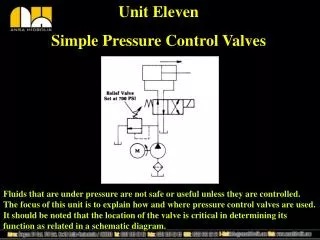
Unit Eleven Simple Pressure Control Valves Fluids that are under pressure are not safe or useful unless they are controlled. The focus of this unit is to explain how and where pressure control valves are used. It should be noted that the location of the valve is critical in determining its function as related in a schematic diagram.
Basic Valve Symbol In Out The above symbol is representative of both hydraulic and pneumatic pressure controls. The system power source determines the fluid nature of the valve. All pressure controls are interpreted the same way. These valves have two ports, one an inlet and the other an outlet, as indicated by the directional arrow. The “dashed” line represents a pressure sensing capability.
Hydraulic and Pneumatic Pressure Control Valves Pictured above are two pressure controls most often discussed in fluid power. On the left is a relief valve used in hydraulics systems and on the left, a pressure regulator used in pneumatics. Their schematic symbols are similar .
Hydraulic and Pneumatic Pressure Control Valves At a glance the two valve symbols above look the same but they are very different. The one on the left is normallynot passing and the one on the right normally passing. Also, the sense lines are located in different ports. You can see that failure to identify these small differences can cause confusion.
Pressure Adjustment In general pressure control valves that can be adjusted have the arrow through the spring diagonally as shown but if the arrow is not present then the valve is considered not adjustable. Usually, not adjustable valves have a lock nut or some other such device to prevent hand adjustment.
Uses of a Normally Closed (not passing)Pressure Control Valve In the circuit above, the pressure control ensures that fluid reaches the actuator at maximum pump flow until a resistance is encountered that exceeds the tension of the spring. When the tension of the spring, due to pressure build up, has been reached, oil will move over the relief valve back to tank. System pressure is equal to the tension of the spring. This is a relief valve function.
Sequence Valve In the circuit pictured above, a second pressure control valve appears in series between the DCV and one of the actuators. This arrangement ensures that the drill cylinder cannot move until the clamp has fully extended.
Counterbalance Valve In the circuit above, gravity acts on the platen to generate a pressure on the rod side of the cylinder. If there was nothing to resist the movement of oil from the rod side, the platen could speed the piston away from incoming oil and slam into the work surface below. By using the incompressible nature of oil we can slow a heavy platen by the use of back pressure.
Counterbalance Valve Back pressure can also be used to slow a motor whose shaft is being driven by the inertia of a flywheel. The back pressure generated is relative to spring tension as is the stopping speed.
Pressure Reducing Valve In this circuit the clamp cylinder must hold a part that could be damaged by full system pressure. The pressure reducing valve senses pressure downstream and closes when the limit of the spring is reached. Fluid must be able to enter a volume in order for pressure to increase so by cutting off flow to the volume, a cylinder in this case, the pressure and clamping force are controlled.
Drains Drains are only found in hydraulic pressure control valves. Since hydraulic pressure control valves use an internal member that allows some bypass leakage, a way of releasing that leakage oil is needed. As the diagrams above indicate, there exists an area above the spool that could fill with oil and “lock” up the valve. To prevent the lock up we provide one of two ways for leakage oil to escape the valve. If the valve does not have pressure on the secondary port, it may be drained internally to the secondary port. In the case of all pressure control valves whose secondary port is under pressure, the valve must be drained externally through an additional port.
Direct and Remote Operation A valve that senses pressure only from its inlet or out port is said to be directly operated as opposed to one that senses pressure from another location which would be called remotely operated. Usually, remote operated valves are referred to as unloading valves.
Unloading Valve Unloading valves are used in hydraulic circuits to momentarily “dump” the flow of the pump back to tank during periods of machine idle time. This reduces heat and saves energy since the load on the prime mover is reduced.
Hi-Lo System Note position of unloading valve. The purpose of the Hi-Lo system is to provide momentary high flow for traverse action but then reduce it for feed rate. A ram, for example, with a long stroke could be moved at a high rate of speed to approach a work piece and then slowed to a crawl before contact thus increasing the cycle time of the machine. Both pumps are used for high flow and the large one “dumped” for low flow.
Remotely Operated Counterbalance Valve In a previous slide a counterbalance valve was shown as directly operated. In actual practice a counterbalance valve might be remote operated as above. The reason for remote operation is reduce lost energy as a result of back pressure.
Brake Valve A real brake valve is more complicated than a simple pressure control. It has two sense lines that compare inlet and outlet pressures. It is assumed by design that when a pressure is present at the inlet port that the motor should turn. The pressure at the inlet causes a “piston” to move against a spool and to hold the valve open for free movement of the motor. The moment the pressure drops at the inlet port the piston allows the spool with its spring to take over and begin to apply back pressure to slow down the motor shaft and its load.
Reverse Flow As you may have noticed, the sequence valve, like many others, can only sense pressure from one port. For fluid to get around the valve on return, a check valve is added. The check valve allows normal operation to take place as fluid is moving toward the cap end of the actuator. However, when fluid is leaving the cap end the cylinder is in retraction and the function of the sequence valve is not needed. Without the check valve, fluid would not be able to get around the valve and the cylinder would lock up.
Pressure Control Valves in General 1. If a pressure control valve has pressure on its secondary port, it must be externally drained. 2. If the secondary port of a pressure control valve is not under pressure, it will usually be internally drained. 3. Check valves are used to bypass flow around normally not passing pressure controls.
Completed Valve Symbols In the following slides, schematic valve symbols appear in their completed form. Their simple form was used to introduce them in a non-intimidating manner. In the industry, this is how they really appear. Study each in detail.
Pressure Regulator Pressure regulators are normally found at the beginning of branch line circuits. Typically, the pressures required by branch line circuits are much lower than the air pressure at the receiver tank. A venting type regulator is one that can exhaust air from its secondary port if pressure exceeds the spring setting.