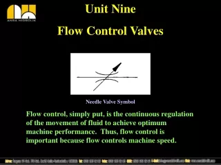
FLOW CONTROL VALVES
FLOW CONTROL VALVES. ATM 322 – Pneumatics Module 4 . WARM UP. VIDEO . Objectives. Explain the function of the one way flow control valve. Describe the main parts of the one way flow control valve. Adjust the one way flow control valve to the required actuator speed.

FLOW CONTROL VALVES
E N D
Presentation Transcript
FLOW CONTROL VALVES ATM 322 – Pneumatics Module 4
Objectives • Explain the function of the one way flow control valve. • Describe the main parts of the one way flow control valve. • Adjust the one way flow control valve to the required actuator speed. • Explain the function of a quick exhaust valve. • Identify the main types of flow control used with double acting cylinder • Draw the required circuit diagram that controls the speed of the forward stroke of a double acting cylnder. • Simulate the pneumatic circuit that controls the speed of the forward stroke of the double acting cylinder using FluidSIM software. • Explain the difference between the one way flow control valve and the quick exhaust valve.
One – Way Flow Control Valve • Controls the flow rate in one direction only & allows free flow in the opposite direction. I.S.O Symbol
Construction of the One – Way Flow Control Valve • The One way Flow Control valve consists of: Check valve + Throttle valve = One- way FCV + =
Construction of the One – Way Flow Control Valve If the flow is from (P) to (A), the check valve stops the flow passing in this direction and the flow then passes through the throttle valve. The cross-section of the throttle is adjustable via a regulator screw. If the flow is in the opposite direction from (A) to (P), the check valve permits the flow freely from (1) to (2)
Control the speed of the cylinder in the advance stroke • SUPPLY AIR THROTTLING • In the case of supply air throttling, the one-way flow control valves are installed such that air being fed to the cylinder is restricted. • Exhaust air can escape freely via the 5/2 way valve. • Supply air throttling is used for single acting cylinders and small volume double acting cylinders.
Control the speed of the cylinder in the advance stroke • EXHAUST AIR FLOW CONTROL • In the case of exhaust air throttling, supply air flows freely to the cylinder and the flow control in the exhaust line resists the escaping air.The piston is held between two air cushions. • Exhaust air throttling should always be used for large double acting cylinders with long strokes. And when the loads are not constant.
Practical Task 1:Controlling the speed of a single Acting cylinder • The following items are required to complete this task: 1) Single acting cylinder 2) 3/2 way valve N/C 3) One way flow control valve 4) Pressure supply
Practical Task 1:Controlling the speed of a single Acting cylinder PROCEDURES: 1-Prepare the components according to the components list. 2- Mount all components according to the Pneumatic circuit. 3- Connect pneumatic tubes according to the pneumatic circuit. 4- Check all parts are connected properly with each other. 5- Switch on the service unit. 6- Start the circuit and check the operation. 7- Turn off the service unit. 8- Dismantle and tidy up.
Function of the Quick Exhaust Valve • In many applications especially with single acting cylinders, it is a common practice to increase the piston speed during retraction of the cylinder to save the cycle time. • This is carried out by incorporating a Quick exhaust valve.
Function of the Quick Exhaust Valve The Output port 2 is directly fitted on to the working port of cylinder. Supply port 1, is connected to the output of the final control element (Directional control valve). The exhaust port 3 is left open to the atmosphere
Way of Operation • Compressed air flows from the directional control valve to the cylinder via the quick exhaust valve from port (1) to port (2). • Exhaust port 3 is closed at this time. • When pressure at port 1 drops, exhaust flow occurs from port (2) to port (3). • In order to implement optimized quick exhaust, the valve must be connected directly to the cylinder’s supply port.
Practical Task 2: Controlling the cylinder return stroke by using a quick exhaust valve • Required items for completing this task are: 1) Single – acting cylinder. 2) 3/2 way valve N\C 3) Quick exhaust valve
Practical Task 2: Controlling the cylinder return stroke by using a quick exhaust valve Procedures: 1- Prepare the components according to the equipments list. 2- Mount all components according to Pneumatic circuit. 3- Connect pneumatic tubes according to the pneumatic circuit. 4- Check all parts are connected properly with each other. 5- Switch on the service unit. 6- Start the circuit. 7- Turn off the service unit 8- Dismantle and tidy up.
Practical Task 3: Actuating a shut off Valve • Task Description: A gate valve operated by double acting cylinder is used in controlling a filling system for plastic pellets. The gate valve needs to be closed quickly during the forward stroke of the double acting cylinder. However, it should be opened slowly during the backward stroke of the double acting cylinder. A double pilot (memory) valve should be used to operate the double acting cylinder.
Practical Task 3: Actuating a shut off Valve Task Requirements: 1. Draw pneumatic circuit diagram 2. Simulate the circuit using FluidSIM software. 3. Assemble the circuit practically and check its operation.
For Further Reading: 1)www.Fest-didactic.com 2)http://www.eng2all.com/vb/t28932.html 3)http://www.logiclab.hu/lesson.php?fe=2