Decoders
Decoders. Decoders. A decoder is multiple-input, multiple-output logic circuit that converts coded inputs into coded outputs . Input code with fewer bits than the output bits. Typically n inputs decoder has 2 n outputs 2-to-4, 3-to-8, 4-to-16, etc. There is a one-to-one mapping.

Decoders
E N D
Presentation Transcript
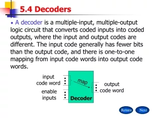
Decoders • A decoder is multiple-input, multiple-output logic circuit that converts coded inputs into coded outputs. • Input code with fewer bits than the output bits. • Typically n inputs decoder has 2n outputs • 2-to-4, 3-to-8, 4-to-16, etc. • There is a one-to-one mapping.
Decoders • General decoder structure • Typically n inputs decoder has 2n outputs • 2-to-4, 3-to-8, 4-to-16, etc.
Binary 2-to-4 decoder Note “x” (don’t care) notation.
Decoder applications • Microprocessor memory systems • selecting different banks of memory • Microprocessor input/output systems • selecting different devices • Microprocessor instruction decoding • enabling different functional units • Memory chips • enabling different rows of memory depending on address • Lots of other applications
Decoding Circuits • Have to be able to decode particular combinations of input signals. • Need to decode the address lines to determine where the data is to go. • Used to transfer data from or to memory or peripherals. • Take a number of input signals and provide enough outputs to indicate what the input was.
Decoding Circuits • If the input is two binary signals, there would have to be four outputs. • One output for each input combination.
Two Bit Decoder D1 D0 0 1 2 3 0 0 0 1 1 0 1 1
MSI 2-to-4 decoder • Input buffering (less load) • NAND gates (faster)
Decoder cascading 4-to-16 decoder
More cascading 5-to-32 decoder
Decoder ICs • 74138 Octal decoder (3-line-to-8-line) • 74154 hex decoder (4-line-to-16-line) • 7442 BCD (Binary Coded Decimal) decoder (4-to-10) • 7447 BCD to seven-Segment decoder (4-line-to-7-line)
Three-state buffers • Output = LOW, HIGH, or Hi-Z. • Can tie multiple outputs together, if at most one at a time is driven.
Three-state buffers • When the enable input is not asserted, the device output “floats”; that is, it goes to a high-impedance (Hi-Z), disconnected state and functionally behaves as if it weren’t even there.
timing • Typically three-state devices are designed so that they go into the Hi-Z state faster than they come out of the Hi-Z state. • That ensures the first device to get off the party line before the second one gets on. • Otherwise excessive current will flow. • The safe way to use three-state devices is to design control logic that guarantees a dead time, during which no one is driving the party line.