Decoders
Decoders. Outline. Useful MSI circuits Decoders Implementing Functions with Decoders Decoders with Enable Larger Decoders Standard MSI Decoders Implementing Functions with Decoders. Outline. Useful MSI circuits Decoders Implementing Functions with Decoders Decoders with Enable

Decoders
E N D
Presentation Transcript
Outline • Useful MSI circuits • Decoders • Implementing Functions with Decoders • Decoders with Enable • Larger Decoders • Standard MSI Decoders • Implementing Functions with Decoders
Outline • Useful MSI circuits • Decoders • Implementing Functions with Decoders • Decoders with Enable • Larger Decoders • Standard MSI Decoders • Implementing Functions with Decoders
decoder encoder mux output data demux data entity input code entity code select select Useful MSI circuits • Four common and useful MSI circuits are: • Decoder • Encoder • Demultiplexer • Multiplexer • Block-level outlines of MSI circuits:
Outline • Useful MSI circuits • Decoders • Implementing Functions with Decoders • Decoders with Enable • Larger Decoders • Standard MSI Decoders • Implementing Functions with Decoders
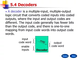
Decoders (1/5) • Codes are frequently used to represent entities, e.g. your name is a code to denote yourself (an entity!). • These codes can be identified (or decoded) using a decoder. Given a code, identify the entity. • Convert binary information from n input lines to (max. of) 2n output lines. • Known as n-to-m-line decoder, or simply n:m or nm decoder (m 2n). • May be used to generate 2n (or fewer) minterms of n input variables.
2x4 Dec F0 F1 F2 F3 Bulb 0 Bulb 1 Bulb 2 Bulb 3 2-bit code X Y Decoders (2/5) • Example: if codes 00, 01, 10, 11 are used to identify four light bulbs, we may use a 2-bit decoder: • This is a 24 decoder which selects an output line based on the 2-bit code supplied. • Truth table:
F0 = X'.Y' F1 = X'.Y F2 = X.Y' F3 = X.Y X Y Decoders (3/5) • From truth table, circuit for 24 decoder is: • Note: Each output is a 2-variable minterm (X'.Y', X'.Y, X.Y' or X.Y)
F0 = x'.y'.z' F1 = x'.y'.z F2 = x'.y.z' F3 = x'.y.z F4 = x.y'.z' F5 = x.y'.z F6 = x.y.z' F7 = x.y.z x y z Decoders (4/5) • Design a 38 decoder. • Application? • Binary-to-octal conversion.
n-bit code n to 2n decoder up to 2n output lines : : Decoders (5/5) • In general, for an n-bit code, a decoder could select up to 2n lines:
Outline • Useful MSI circuits • Decoders • Implementing Functions with Decoders • Decoders with Enable • Larger Decoders • Standard MSI Decoders • Implementing Functions with Decoders
Decoders: Implementing Functions (1/5) • A Boolean function, in sum-of-minterms form a decoder to generate the minterms, and an OR gate to form the sum. • Any combinational circuit with n inputs and m outputs can be implemented with an n:2n decoder with m OR gates. • Good when circuit has many outputs, and each function is expressed with few minterms.
3x8 Dec 0 1 2 3 4 5 6 7 S x S2 S1 S0 y C z Decoders: Implementing Functions (2/5) • Example: Full adder S(x, y, z) = S m(1,2,4,7) C(x, y, z) = S m(3,5,6,7)
0 0 0 0 0 3x8 Dec 0 1 2 3 4 5 6 7 S x S2 S1 S0 y C z Decoders: Implementing Functions (3/5) 1 0 0 0 0 0 0 0
1 0 0 1 0 3x8 Dec 0 1 2 3 4 5 6 7 S x S2 S1 S0 y C z Decoders: Implementing Functions (4/5) 0 1 0 0 0 0 0 0
1 1 1 1 1 3x8 Dec 0 1 2 3 4 5 6 7 S x S2 S1 S0 y C z Decoders: Implementing Functions (5/5) 0 0 0 0 0 0 0 1
Outline • Useful MSI circuits • Decoders • Implementing Functions with Decoders • Decoders with Enable • Larger Decoders • Standard MSI Decoders • Implementing Functions with Decoders
F0 = EX'Y' F1 = EX'Y F2 = EXY' F3 = EXY X Y E Decoders with Enable (1/2) • Decoders often come with an enable signal, so that the device is only activated when the enable, E=1. • Truth table: • Circuit:
Decoders with Enable (2/2) • In the previous slide, the decoder has a one-enable signal, that is, the decoder is enabled with E=1. • In most MSI decoders, enable signal is zero-enable, usually denoted by E’ (or E). The decoder is enabled when the signal is zero. Decoder with 1-enable Decoder with 0-enable
Outline • Useful MSI circuits • Decoders • Implementing Functions with Decoders • Decoders with Enable • Larger Decoders • Standard MSI Decoders • Implementing Functions with Decoders
3x8 Dec 0 1 : : 7 F0 = w'x'y' F1 = w'x'y : : F7 = wxy w x y S2 S1 S0 2x4 Dec w x y 0 1 2 3 F0 = w'x'y' F1 = w'x'y F2 = w'xy' F3 = w'xy S1 S0 E 2x4 Dec 0 1 2 3 F4 = wx'y' F5 = wx'y F6 = wxy' F7 = wxy S1 S0 E Larger Decoders (1/6) • Larger decoders can be constructed from smaller ones. • For example, a 3-to-8 decoder can be constructed from two 2-to-4 decoders (with one-enable), as follows:
3x8 Dec 0 1 : : 7 F0 = w'x'y' F1 = w'x'y : : F7 = wxy w x y S2 S1 S0 1 = enabled 2x4 Dec w x y 0 1 2 3 F0 = w'x'y' F1 = w'x'y F2 = w'xy' F3 = w'xy S1 S0 0 = disabled E 2x4 Dec 0 1 2 3 F4 = wx'y' F5 = wx'y F6 = wxy' F7 = wxy S1 S0 E Larger Decoders (2/6) 0 0 0 1 0 0 0 0 0 0 0
3x8 Dec 0 1 : : 7 F0 = w'x'y' F1 = w'x'y : : F7 = wxy w x y S2 S1 S0 1 = enabled 2x4 Dec w x y 0 1 2 3 F0 = w'x'y' F1 = w'x'y F2 = w'xy' F3 = w'xy S1 S0 0 = disabled E 2x4 Dec 0 1 2 3 F4 = wx'y' F5 = wx'y F6 = wxy' F7 = wxy S1 S0 E Larger Decoders (3/6) 0 0 1 0 1 0 0 0 0 0 0
3x8 Dec 0 1 : : 7 F0 = w'x'y' F1 = w'x'y : : F7 = wxy w x y S2 S1 S0 0 = disabled 2x4 Dec w x y 0 1 2 3 F0 = w'x'y' F1 = w'x'y F2 = w'xy' F3 = w'xy S1 S0 1 = enabled E 2x4 Dec 0 1 2 3 F4 = wx'y' F5 = wx'y F6 = wxy' F7 = wxy S1 S0 E Larger Decoders (4/6) 1 1 0 0 0 0 0 0 0 1 0
4x16 Dec 0 1 : : 15 F0 F1 : : F15 w x y z S3 S2 S1 S0 3x8 Dec w x y z 0 1 : 7 F0 F1 : F7 S2 S1 S0 E 3x8 Dec 0 1 : 7 F8 F9 : F15 S2 S1 S0 E Larger Decoders (5/6) • Construct a 4x16 decoder from two 3x8 decoders with 1-enable.
Larger Decoders (6/6) • Note: The input, w and its complement, w', is used to select either one of the two smaller decoders. • Decoders may also have zero-enable and/or negated outputs. (Normal outputs = active high; negated outputs = active low.) • Exercise: What modifications must be made to provide an ENABLE input for the 3x8 decoder (2 slides ago) and the 4x16 decoder (previous slide) created? • Exercise: How to construct a 4x16 decoder using five 2x4 decoders with enable?
Outline • Useful MSI circuits • Decoders • Implementing Functions with Decoders • Decoders with Enable • Larger Decoders • Standard MSI Decoders • Implementing Functions with Decoders
Standard MSI Decoders (1/2) • 74138 (3-to-8 decoder) 74138 decoder module. (a) Logic circuit. (b) Package pin configuration.
Negated outputs Standard MSI Decoders (2/2) 74138 decoder module. (c) Function table. 74138 decoder module. (d) Generic symbol. (e) IEEE standard logic symbol. Source: The Data Book Volume 2, Texas Instruments Inc.,1985
Outline • Useful MSI circuits • Decoders • Implementing Functions with Decoders • Decoders with Enable • Larger Decoders • Standard MSI Decoders • Implementing Functions with Decoders
Decoders: Implementing Functions Revisit (1/2) • Example: Implement the following logic function using decoders and logic gates f(Q,X,P) = m(0,1,4,6,7) = M(2,3,5) • We may implement the function in several ways: (a) Use a decoder (with active-high outputs) with an OR gate: f(Q,X,P) = m0 + m1 + m4 + m6 + m7 (b) Use a decoder (with active-low outputs) with a NAND gate: f(Q,X,P) = ( m0' . m1' . m4' . m6' . m7' )' (c) Use a decoder (with active-high outputs) with a NOR gate: f(Q,X,P) = ( m2 + m3 + m5 )' [ = M2.M3.M5] (d) Use a decoder (with active-low outputs) with an AND gate: f(Q,X,P) = m2' . m3' . m5'
0 1 2 3 4 5 6 7 0 1 2 3 4 5 6 7 3x8 Dec 3x8 Dec Q X P A B C f(Q,X,P) Q X P A B C 0 1 2 3 4 5 6 7 0 1 2 3 4 5 6 7 3x8 Dec 3x8 Dec f(Q,X,P) Q X P A B C Q X P A B C Decoders: Implementing Functions Revisit (2/2) f(Q,X,P) = m(0,1,4,6,7) f(Q,X,P) (a) Active-high decoder with OR gate. (b) Active-low decoder with NAND gate. f(Q,X,P) (c) Active-high decoder with NOR gate. (d) Active-low decoder with AND gate.