
ME: 121 Engineering Practices
ME: 121 Engineering Practices. Precision Measuring Instruments Inside, Depth, Height and Angular Measuring Instruments. Precision Measuring Instruments. VERNIER CALIPER OUTSIDE MICRO METER INSIDE MICROMETER CALIPER INSIDE MICROMETER DEPTH MICROMETER VERNIER HEIGHT GAUGE

ME: 121 Engineering Practices
E N D
Presentation Transcript
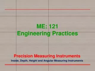
ME: 121Engineering Practices Precision Measuring Instruments Inside, Depth, Height and Angular Measuring Instruments
Precision Measuring Instruments • VERNIER CALIPER • OUTSIDE MICRO METER • INSIDE MICROMETER CALIPER • INSIDE MICROMETER • DEPTH MICROMETER • VERNIER HEIGHT GAUGE • VERNIER DEPTHGAUGE
Outside Micrometers • A micro meter is a precision instrument used to measure ajob, generally within an accuracy of 0.01mm • Micrometer used to take the outside measurements are know as outside micrometer. • Principle :- The Micrometer works on the principle of screw and nut. The linear movement of the spindle during one rotation is equal to the pitch of screw.
Outside Micrometers • Uses :- Precision Outside linear measurement English 0-1”, 1”-2”, 2”-3”...... up to 12”. 12”-16”, 16”-20”, 20”-24”. Metric 0 – 25 mm, 25 – 50 mm, 50 – 75 mm, 75 – 100 mm Ranges
1. Frame :- The frame is made of Cast iron on which the whole assembly is attached. 2. Barrel/Sleeve:- Main scale is graduated on it with 0.5 mm distance. 3 2 1 3. Thimble:- Divisions are marked on this cylindrical portion. Knurling is made on it for better gripping. Construction of Outside Micrometers
6 4 5 7 Construction of Outside Micrometers 4. Spindle:- Spindle is one of the contacting surface during measurement. It moves to and fro as thimble rotated. 5. Anvil:- It is the another contacting surface which is fixed in Frame. 6. Lock nut:- This nut is used to lock the movement of the spindle. 7. Ratchet:- Ratchet is used to apply uniform pressure during measurement.
Construction of Outside Micrometers anvil spindle sleeve thimble ratchet frame
In metric micrometer the pitch of the spindle thread is 0.5 mm. Thereby in one rotation of the thimble, the spindle advances by 0.5 mm. On the barrel a 25 mm long datum line is marked. This line is further graduated to millimeters (1 mm) and half millimeters (0.5 mm). The graduations are numbered as 0, 5, 10, 15, 20 and 25 mm. Barrel graduation Graduation of Outside Micrometers
Graduation of Outside Micrometers The circumference of the bevel edge of the thimble is graduated into 50 divisions The distance moved by the spindle during one rotation of the thimble is 0.5 mm. Thimble graduation
Reading of Outside Micrometers Least Count of Outside Micrometer The least count of a Metric Micrometer is 0.01 mm. It is the ratio of value of 1 main scale division and total graduations on thimble. i.e. 0.5/50 Zero Error of Outside Micrometer When the anvil and spindle of the micrometer touch each other, the scales should read zero. If not, there is a zero error in the micrometer.
} 2 divisions Zero Error of Outside Micrometer If the anvil and spindle touch each other, but the scales do not read zero as shown below, the zero error is positive. supposing observed reading is 2.37 mm, then corrected reading = observed reading – zero error = 2.37 – (+0.02) = 2.35 mm
Zero Error of Outside Micrometer If the anvil and spindle touch each other, but the scales do not read zero as shown below, the zero error is negative. } 3 divisions supposing observed reading is 2.87 mm, then corrected reading = observed reading – zero error = 2.87 – (-0.03) = 2.90 mm
Example 1, Reading of Outside Micrometers • In given figure first read the barrel graduation. Which is 13. i.e. 13 mm. • Half millimeter is also visible. Thus 13.00 mm + 00.50 mm 13.50 mm
Example 1, Reading of Outside Micrometers Next read the thimble graduation, which is 13. Multiply it by L.C. which is 0.01mm. = 13 x 0.01 mm = 0.13mm. • Summation of all above readings,13.50mm +0.13mm 13.63mm
Example 3, Reading of Outside Micrometers sleeve thimble reading on sleeve = 4.5 mm reading on thimble = 0.12 mm actual reading of object = 4.5 + 0.12 = 4.62 mm
Practice Problems, English Micrometer How to Read 0 -1” Micrometer
Inside Measuring Instruments All inside measuring instruments fall into TWO categories Direct Reading Instruments: The size of the hole can be read on the instrument being used to measure the hole, e.g. Inside Micrometers, the Intrimik, and the Vernier Caliper. The Intrimik Transfer Type Instruments: Set to the diameter of the hole and then this size is transferred to an outside micrometer to determine the actual size, e.g. Inside Calipers, Small Hole Gages and Telescope Gages
Direct (Inside) Measuring Instruments • Inside Micrometer Caliper • The inside micrometer caliper is designed for measuring holes, slots and grooves, from .200 to 2.000 in. in size or 5 to 50 mm in size. • The inside micrometer caliper is based on the same principle as the standard micrometer, except that the Barrel readings on some calipers are reversed.
Direct (Inside) Measuring Instruments To Use an Inside Micrometer Caliper Adjust the Jaws to slightly less than the diameter to be measured Hold the fixed jaw against one side of the hole and adjust the moveable jaw until the proper “Feel” is obtained Move the moveable jaw back and forth to ensure that the measurement taken is across the true diameter Set the lock nut, remove the instrument, and check the reading.
Direct (Inside) Measuring Instruments Inside Micrometers • For internal measurement larger than 1.500 in. or 40 mm, inside micrometers are used. • The inside micrometer set consists of a micrometer head, having a range .500 or 1 in.; several extension rods of different lengths, which may be inserted into the head; and a .500 in. spacing collar. These sets cover the range from, 1.500 in. to over 100 in., or from 40 to 1000 mm for metric tools.
Direct (Inside) Measuring Instruments To Measure with an Inside Micrometers Measure the size of the hole with a rule. Insert the correct micrometer extension rod. Align the zero marks on the rod and micrometer head. Hold the rod firmly against the micrometer head and tighten the knurled set screw. Adjust the micrometer to slightly less than the diameter to be measured. Hold the head in a fixed position and adjust the micrometer to the hole size while moving the rod end in the direction of the arrows. Carefully remove the micrometer and note the reading. To this reading, add the length of the extension rod and collar. Using an inside micrometer to measure the size of a hole
Direct (Inside) Measuring Instruments Reading Inside Micrometers The inside micrometer reads in the same manner as the standard micrometer. Since there is no locking nut on the inside micrometer, the thimble nut is adjusted to a tighter fit on the spindle thread to prevent a change in the setting while it is being removed from the hole. • Used for measuring cylinder bores, housing bores • Screw pitches same as outside micrometer
Direct (Inside) Measuring Instruments Intrimik A difficulty encountered in measuring hole sizes with instruments employing only two measuring faces is that of properly measuring the diameter and not a chord (a group of notes, usually three or more surrounded together in harmony) of the circle. An instrument that eliminates this problem is the Intrimik. The Intrimik consists of a head with three contact points spaced 1200 apart; this head is attached to a micrometer-type body. The contact points are forced out to contact the inside of the hole by means of a tapered or conical plug attached to the micrometer spindle. The construction of a head with three contact point permits the Intrimik to be self-centering and self aligning. Construction of the Intrimik head The Intrimik, which has three contact points, measures holes accurately
Direct (Inside) Measuring Instruments Intrimik Ranges and Accuracy The range of these instruments is from .275 to 12.000 in., and the accuracy varies between .0001 and .0005 in., depending on the head used. Metric Intrimik have a range from 6 to 300 mm, with graduations in 0.001 mm. The accuracy of the Intrimik should be checked periodically with a setting ring or master ring gage. It is more accurate than other methods because it provides a direct reading, eliminating the necessity of transferring measurements to determine hole size as with telescope or small hole gages
Transfer Type (Inside) Instruments Telescope Gages Telescope gage are used to obtain the size of holes, slots, and recesses from .3125 to 6.000 in. (8 to 152 mm). They are T-shaped instruments, each consisting of a pair of telescoping tubes or plungers connected to a handle. The plungers are spring-loaded to force them apart. The knurled knob on the end of the handle locks the plungers into position when it is turned in a clockwise direction.
Transfer Type (Inside) Instruments To Measure Using a Telescope Gage • Measure the hole size and select the proper gage. • Clean the gage and the hole. • Depress the plungers until they are slightly smaller than the hole diameter and lightly tighten the knurled knob. • Insert it into the hole and, with the handle tilted upward slightly, loosen the knurled knob to release the plungers. • Lightly snug up the knurled knob. • Hold the bottom leg of the telescope gage in position with one hand. • Move the handle downward through the center while slightly moving the top leg from side to side • Tighten the knurled knob to lock the plungers in position. • Recheck the "feel" on the gage by testing it in the hole again. • Check the gage size with outside micrometers, maintaining the same "feel" as in the hole
Transfer Type (Inside) Instruments In transfer measurement the size of an object is taken with an instrument which is not capable of giving a direct reading. The size is then determined by measuring the setting of the instrument with a direct-reading instrument or gage of a known size. Small Hole Gages Small hole gages are available in sets of four, covering a range from .125 to .500 in (3 to 13 mm). They are manufactured in two types The small hole gages have a small, round end, or ball, and are used for measuring holes, slots, grooves, and recesses that are too small for inside calipers or telescope gages. The Small hole gages with a Flat Bottom are used for similar purposes. The flat bottom permits the measurement of shallow slots, recesses, and holes impossible to gage with the rounded type.
Transfer Type (Inside) Instruments Both types are of similar construction and are adjusted to size by turning the knurled knob on the top. This draws up a tapered plunger, causing the two halves of the ball to open up and contact the hole. • To Use a Small Hole Gage • Small hole gages require extreme care in setting, since it is easy to get an incorrect setting when checking the diameter of a hole. • Follow this procedure: • Measure the hole to be checked with a rule. • Select the proper small hole gage. • Clean the hole and the gage. • Adjust the gage until it is slightly smaller than the hole and insert it into the hole. • Adjust the gage until it can be felt just touching the sides of the hole or slot. • Swing the handle back and forth, and adjust the knurled end until the proper "feel" is obtained across the widest dimension of the ball. • Remove the gage and check the size with an outside micrometer.
Transfer Type (Inside) Instruments Dial Bore Gages • Used for cylinder bores and main bores • Uses ‘comparative’ measurement • Measure differences in the size that was set • Set up in a setting fixture or outside micrometer
Depth Measuring Instruments Although rules and various attachments can be used for measuring depth, the depth micrometer and the depth vernier are most commonly used where accuracy is required. Micrometer Depth Gage Micrometer depth gages are used for measuring the depth of blind holes, slots, recesses, and projections. Each gage consists of a flat base attached to a micrometer sleeve. An extension rod of the required length fits through the sleeve and protrudes (extended) through the base. This rod is held in position by a threaded cap on the top of the thimble.
Depth Measuring Instruments • To Measure with a Micrometer Depth Gage • Remove burrs from the edge of the hole and the face of the workpiece. • Clean the work surface and the base of the micrometer. • Hold the micrometer base firmly against the surface of the work. • Rotate the thimble lightly with the tip of one finger in a clockwise direction until the bottom of the extension rod touches the bottom of the hole or recess. • Recheck the micrometer setting a few times to make sure that not too much pressure was applied in the setting. • Carefully note the reading. • Note: The numbers on the thimble and the sleeve are the reverse of those on a standard micrometer.
Depth Measuring Instruments • Vernier Depth Gage • The depths of holes, slots, and recesses may also be measured by a vernier depth gage. This instrument reads in the same manner as a standard vernier caliper. • Depth measurements may also be made with certain types of vernier or dial calipers that are provided with a thin sliding blade or depth gage attached to the movable. • The blade protrudes from the end of the bar opposite the sliding jaw. • The caliper is placed vertically over the depth to be measured, and the end of the bar is held against the shoulder while the blade is inserted into the hole to be measured. • Depth readings are identical to standard vernier readings.
Flat Surfaces • A surface plate is a solid, flat plate used as the main horizontal reference plane for precision inspection, marking out (layout), and tooling setup. • The surface plate is often used as the baseline for all measurements to the workpiece, therefore one primary surface is finished extremely flat with accuracy up to .00001"/.00025 mm. • Surface plates are a very common tool in the manufacturing industry and are often permanently attached to robotic type inspection devices such as a coordinate-measuring machine. • Types: • Granite • Cast iron • Glass
Height Measuring Instruments Accurate height measurement is very important in layout and inspection work. With the proper attachments, the vernier height gage is a very useful and versatile tool for these purposes. Where extreme accuracy is required, gage blocks or a precision height gage may be used. Vernier Height Gage • These instruments are available in a variety of sizes-from 12 to 72 in. or from 300 to 1000 mm-and can be accurately set at any height to within .001 in. or 0.02 mm, respectively. • Basically, a vernier height gage is a vernier caliper with a hardened, ground, and lapped base instead of a fixed jaw and is always used with a surface plate or an accurate flat surface. • The sliding jaw assembly can be raised or lowered to any position along the beam. • Fine adjustments are made by means of an adjusting nut. • The vernier height gage is read in the same manner as a vernier caliper.
Height Measuring Instruments • The vernier height gage is very well suited to accurate layout work and may be used for this purpose if a scriber is mounted on the movable jaw. • The offset scriber is a vernier height gage attachment that permits setting heights from the face of the surface plate. When using this attachment, it is not necessary to consider the height of the base or the width of the scriber and clamp. The scriber reaches below the gage base
Height Measuring Instruments The digital height gage has an easy to read display that can be very quickly set to any dimension. The readout display is in .0001 in. (0.002 mm), and it has a zero function that allows the zero to be set at any position on the job or workpieces. This type of height gage is becoming very popular because it eliminates or reduces the errors common to height gages having vernier scales. A depth gage attachment may be fastened to the movable jaw, permitting the measurement of height differences that may be difficult to measure by other methods. Another important use for the vernier height gage is in inspection work. A dial indicator may be fastened to the movable jaw of the height gage, and distances between holes or surfaces can be checked to within an accuracy of .001 in. (0.02 mm) on the vernier scale.
Angular Measurement Instruments Universal Bevel Protractor The universal bevel protractor is a precision instrument capable of measuring angles to within 5' (5 minutes) or (0.083°). • vernier scale • protractor dial, graduated in degrees with every tenth degree numbered • A sliding blade is fitted into this dial; it may be extended in either direction and set at any angle to the base. • The blade and the dial are rotated as a unit
Angular Measurement Instruments • Universal Bevel Protractor • The vernier scale is divided into 12 spaces on each side of the 0 line, which occupy the same space as 23° the protractor dial. • By simple calculation, it is easy prove that one vernier space is 5', or less than two graduations on the main scale. • If zero on the vernier scale coincides with a line on the main scale, the reading will be degrees only. • However, if any other line on the venier scale coincides with a line on the main scale, the number of vernier graduations beyond the zero should be multiplied by 5 and added to the number of full degrees indicated on the protractor dial.
Angular Measurement Instruments Universal Bevel Protractor The reading is Number of full degrees = 50° Value of vernier scale (4 X 5') = 20' Reading = 50°20' Note: A double-check of the reading would locate the vernier scale line on the other side of zero, which coincides with a protractor scale line. This line should always equal the complement of 60'. In Fig. the 40' line to the right of the zero coincides with a line on the protractor scale. This reading, when added to the 20' on the left of the scale, is equal to 60', or 1°.
Angular Measurement Instruments Combination Set