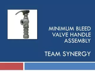
Cockpit Assembly Team
Cockpit Assembly Team. Victor Calamaro , Nick Flanagan, Rashaud Harvey, Danielle Painter. Customer Needs. Instrument the existing throttle lever with position transducers Maintain control mechanisms such as pilot interface handles, range of motion and feel


Cockpit Assembly Team
E N D
Presentation Transcript
Cockpit Assembly Team Victor Calamaro, Nick Flanagan, RashaudHarvey, Danielle Painter
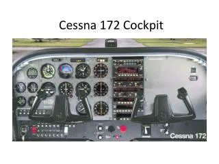
Customer Needs • Instrument the existing throttle lever with position transducers • Maintain control mechanisms such as pilot interface handles, range of motion and feel • Instrument the existing rudder pedals with displacement and force transducers • Maintain control mechanisms such as pilot interface pedals, range of motion and feel • Instrument the existing yoke with displacement (axial and rotational) and force transducers • Maintain control mechanisms such as pilot interface grips, range of motion and feel • Enable feedback from all transducers (force, spring rate and drag)
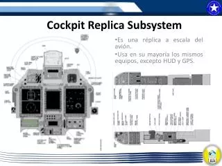
Customer Needs (cont.) • Install LCD monitor in front of each pilot station (2) • Implement an emergency stop function in multiple locations that will allow a given simulation to reset if one operation fails • Two wire (signal and return) cable • Two emergency stop switches located at each pilot station • Two switches made available for ground personnel • Clear labeling of switch function • Pull to operate, push to stop Install cabling from all transducers and monitors to the ground Interface connector for easy disconnect/replacement Rout cabling to ventilation tube and wire way conduit Provide a minimum of 10ft cabling beyond conduit exit Install mounting system for side stick inceptor. Design elbow and wrist assembly for pilot comfort
Engineering Specifications • Rudder sensor must output a position signal from 0 to 5 V • Throttle sensor must output a position signal from 0 to 5 V • Yoke sensors must output a position and rotation signal from 0 to 5 V • All controls provide X lbf feedback • Monitors are mounted in cockpit (yes/no measurement) • Emergency stop resets simulation (yes/no measurement) • All cabling is able to reach computer system (yes/no measurement) • Items in italics need to be determined
Overview • Yoke Drawback • Yoke Rotation • Throttle • LCD Display • Rudder Pedals
Pugh Matrix Weighting • Ease of Maintenance • How easy is it to get to the sensor if there is problems? • Importance - Medium • Accuracy • How close does the sensor measure position? • Importance - High • Ease of Installation • How easy is it to mount the sensor? • Importance - High • Durability • How often will the sensor need to be replaced? • Importance - Medium • Cost • How much does the sensor and associated signal conditioning cost? • Importance - Low
Yoke Drawback – Sensor Type • LVDT • Type dependent on mounting location • Most reliable, most expensive • Encoder • Similar in cost, still reliable • Quadrature Output • String Potentiometer • Type dependent on mounting location • Cheap, will wear out
Yoke Drawback – Mounting Location • Connected to yoke shaft itself • Most direct -> could be most accurate • Complex geometry causes problems • Attached to cable • Simplest • Least direct -> chance for cables to slip etc -> chance for lower accuracy
Yoke Drawback – Signal Conditioning • LVDT • Requires an expensive signal conditioning board to output 0 to 5V • Board produced by Moog • Analog board can be made • Encoder • Requires a less expensive signal conditioning board to output 0 to 5V • String Potentiometer • No conditioning necessary
Yoke Rotation – Sensor Type • RVDT/LVDT • Type dependent on mounting location • Most reliable, most expensive • Encoder • Less expensive, still reliable • Quadrature Output • Rotational/String Potentiometer • Type dependent on mounting location • Cheap, will wear out
Yoke Rotation – Mounting Location • On yoke itself • Most direct -> could be most accurate • Complex geometry causes problems • On Pulley for cables • Less direct -> slightly less accurate then on the yoke • Easier to mount then on yoke • Attached to cable • Simplest • Least direct -> chance for cables to slip etc -> chance for lower accuracy
Yoke Rotation – Signal Conditioning • RVDT/LVDT • Requires an expensive signal conditioning board to output 0 to 5V • Board produced by Moog • Analog board can be made • Encoder • Requires a less expensive signal conditioning board to output 0 to 5V • Rotational/String Potentiometer • No conditioning necessary
Throttle- Sensor Technology • Encoder • Easy installation • Durable • LVDT • Requires Signaling Board • Accurate • RVDT • Accurate • Easy installation
Throttle-Mounting Location • Between Throttle Levers • Durable • Accurate • Easily accessible
Throttle-Signaling Condition • RVDT/LVDT • Requires an expensive signal conditioning board to output 0 to 5V • Board produced by Moog • Analog board can be made • Encoder • Requires a less expensive signal conditioning board to output 0 to 5V
Rudder Pedal-Sensor • String/Rotational Potentiometer • Inexpensive • Wears out • Encoder • Durable • Reliable • LVDT/RVDT • Requires Signaling Board • Expensive • Accurate
Rudder Pedal-Mounting Location • Attached to pedal • Direct • Accessible • Cable Connection • Indirect • Slip possible
Rudder Pedal-Signaling Condition • RVDT/LVDT • Requires an expensive signal conditioning board to output 0 to 5V • Board produced by Moog • Analog board can be made • Encoder • Requires a less expensive signal conditioning board to output 0 to 5V • String/Rotational Potentiometer • No conditioning necessary
LCD Display-Technology • Flat Panel • Durable • Easy Maintenance • Compact • Monitor • Bulky • Easy Installation
LCD Display-Mounting • Bolt on Dash • Easily accessible • Durable • Velcro on Dash • Easily accessible • Cheap • Glue on Dash • Easily accessible • Easy installation