Development of a UAS LIDAR Bathymeter for Monitoring Greenland's Ice Sheet Dynamics
This research proposal aims to devise a cost-effective, high-accuracy method for remotely monitoring the speed and changes in the Greenland ice sheet at a localized scale. By designing a laser sensor to be mounted on a UAS, we intend to measure surface mass balance and flow speed changes in glaciers. Additionally, our laser ranging system will accurately gauge the depth of glacial melt ponds, enabling precise observations of key glaciological variables. This work will also validate data from the Geoscience Laser Altimeter System (GLAS) over the Jakobshavn Isbræ region.


Development of a UAS LIDAR Bathymeter for Monitoring Greenland's Ice Sheet Dynamics
E N D
Presentation Transcript
UAS LIDAR Bathymeter Leyla Safari
The research proposal of this project is to develop a method to remotely monitor the speed and change of the Greenland ice sheet on a localized scale at a low cost and with high accuracy. Research Question
The engineering goal of this project is to design a laser sensor that can be mounted on a UAS (unmanned aerial system) to measure changes in surface mass-balance and flow speed of glaciers. We want to create a laser ranging system that can measure the depth of the glacial melt ponds with very shallow depths and with high accuracy. This capability will enable observations of key glaciological variables within glaciers, including change in ice surface elevation and flow speed at high precision over a large area, and will be used to verify GLAS (Geoscience Laser Altimeter System) data recorded from orbits over the Jakobshavn Isbrea portion of the Greenland ice sheet. Engineering Goals
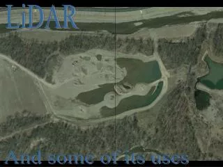
Glacier melt ponds are bodies of water that form on the surface a glacier, caused by the heat of the sun. • During the summer, more ponds are visible due to the increased sun exposure. • They have been found anywhere from a couple of feet wide and deep to miles long and close to 100 ft deep. • It would seem logical that as the summer goes on, these melt ponds only grow in size. Yet scientists have recently found that this is not always the case. In April of 2008, scientists from Woods Hole Oceanographic Institute witnessed almost an entire lake over 2 miles long and 40 feet deep drain in less than an hour and a half in a cascade larger than Niagara Falls. Melt Ponds
Moulins are holes, chutes, or crevasses through which water can travel down through a glacier. • They are formed when the body of water exerts a force on the ice large enough for the openings to form. Once formed, the water quickly travels through it. • The water can travel through the moulin all the way to the bedrock underneath the glacier. It then acts as a sort of lubricant, slightly lifting the glacier and allowing it to move much faster. It can also cause massive chunks from the glacier to break off into the ocean. Moulins
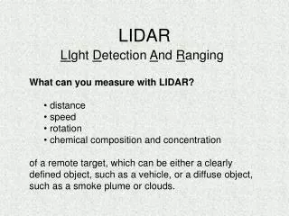
Light Detection And Ranging is an optical remote sensing technology that uses properties of scattered light to produce information about a target. • The most common method is to use laser pulses. It is similar to RADAR, which uses radio waves, and finds the distance between the instrument and the target by measuring the time delay between when the laser pulse is sent and when it comes back. LIDAR
3 9 6 7 8 5 4 2 1 Lab Setup
Laser(1): We use a 14 kHz green laser. It is important that it is green because green light (532 nm wavelength) has a high transmission through water. • Iris(2): Allows us to control amount of laser light getting through. • Pipe(3): This is what we use to put ice and water in to simulate a glacier and collect data using the laser. • Turning Mirror(4): Directs returning laser light towards the PMT. • Iris(5): Same as above. • Turning Mirror(6): Directs laser light. • Iris(7): Same as above • PMT(8): The Photomultiplier Tube, a very sensitive detector that allows us to multiply the very low amounts of laser light coming in by applying a voltage, allowing us to detect even single photons. • Oscilloscope(9): This instrument allows signal voltages to be viewed. The laser light has a voltage, so we can look at the signal the PMT outputs on the scope as a live plot of voltage vs. time. Setup
Simulation of laser pulse off of water surface and bottom of melt pond.
The method that allows us to translate the pulses we receive from the target into the depth of the water is relatively simple. • The laser sends out an initial pulse. Some of this light will bounce off the surface of the water and into the PMT, and some will continue to the ice at the bottom, bounce off that, and return to the PMT. • By looking at the time between these pulses, we can figure out the depth of the water using the equation: d=ct/2 × (1/1.333…) where the depth(d)=speed of light(c) × time(t) ÷ 2 times the indices of refraction of air and water. We divide by 2 because the light goes down and back, and we need only half that distance to have the depth, and the indices of refraction to account for the difference of behavior of the speed of light in air and water Methods
The plot acquired when ranging through a tube with 11.5 inches of water. Since we know the time between the surface return and the bottom return, we use our equation to find the depth: The time difference between peaks is about 0.26 ns d=ct/2 d=(3×10⁻⁸)(0.26)/2 d=.345 m or 15.35 in 15.35 (1/1.3333…)=11.5 in
The plot acquired when ranging through a tube with 8.6 inches of water. The time difference between peaks is about 0.2 ns d=ct/2 d=(3×10⁻⁸)(0.19)/2 d=.285 m or 11.22 in 11.22 (1/1.3333…)= 8.4 in
Ground Resolution: • How do the attitude of the UAV(roll, pitch, and yaw) and the specifications of the laser affect the ground resolution. • Surface Return: • The return from the surface of the water is more intense than from the bottom and overpowers it. Problems
We have a 14 kHz laser that we know creates a .25 m radius circular ground spot at an altitude of 1000 m and the UAV is flying at 25.5 m/s. We can find the distance between 2 shots of the laser by using the following: L 25.5 m x 1 sec = .00182m/shot 1 sec 14000 shots .00182 m .25 m .25 m The length (L) of this ground spot is then equal to: .25m+.25m+.00182m= .50182m The general equation for the Length(L) for any number(n) of ground spots is: Solution-Ground Resolution L(n)=(n-1)(25.5/14000)+.5
There is another component to this problem which is the pulse width of the laser. One shot is .5 ns, and in that time, the UAV travels some distance(d) which blurs the ground spot. 1.275x10⁻⁸ m The pulse width can be accounted for by finding the distance the UAV travels in .5 nanoseconds by using d=rt: d=25.5m/s × 5x10⁻⁸ s d=1.275x10⁻⁸ m Solution-Ground Resolution 1.275x10⁻⁸ m
ѳ ѳ φ Tan(ѳ)=x1/1000 x1=1000*Tan(ѳ) 1000 m 1000 m φ ѳ x1 .25 m 1000 m The divergence angle(φ) can be found by using: φ=tan-1(.25/1000) Ѳ+φ Tan(ѳ+φ)=x2/1000 x2=1000*Tan(ѳ +φ) 1000 m r x2 x1 x2 x2-x1=r Note: This is the same geometry that would be used to find the affect of roll r=1000tan(ѳ +φ)-1000tan(ѳ) Solution-Ground Resolution
The ground resolution variance is negligible in terms of the laser specifications and the attitude of the plane. • It is only possible to accurately measure the depth of water more than about 8 inches deep, because the bottom return pulse is indistinguishable from the surface return any shallower than that. Conclusions
To possibly find a way to be able to range into smaller depths and not be restrained by the specifications of the equipment we are using. • To be able to input data into the HRMTime Software for data acquisition via the CFD(Constant Fraction Discriminator). Future Plans
Bennett, Paul. "Greenland - National Geographic Adventure Magazine." National Geographic - Inspiring People to Care About the Planet Since 1888. National Geographic. Web. 14 Feb. 2010. <http://www.nationalgeographic.com/adventure/adventure-travel/greenland/global-warming-4.html>. Buis, Alan. "NASA - Moulin 'Blanc': NASA Expedition Probes Deep Within a Greenland Glacier." NASA.gov. NASA, 11 Dec. 2006. Web. 14 Feb. 2010. <http://www.nasa.gov/centers/jpl/news/moulin-20061211.html>. Gardiner, Lisa. "Climate Discovery 503: Greenland's Ice Is Melting Faster." Windows to the Universe. UCAR, 22 May 2009. Web. 14 Feb. 2010. <http://www.windows.ucar.edu/tour/link=/earth/climate/greenland_cd503.html&sw=fal>. Lidar Schematic. Digital image. LIDAR Overview. FORSYS. Web. 14 Feb. 2010. <http://forsys.cfr.washington.edu/JFSP06/lidar_technology.htm>. Stroeve, Julienne. Moulin. Digital image. NSIDC Press Room: Expeditions and Field Work. NSIDC, Aug. 2009. Web. 14 Feb. 2010. <http://nsidc.org/news/press/expeditions.html>. Bibliography
Special thanks to Steve Mitchell and Jeff Thayer in the Aerospace Engineering Department at the University of Colorado.