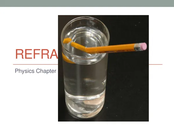
Refraction
Refraction. Glass block. 35 o. Starter. frequency. speed. wavelength.
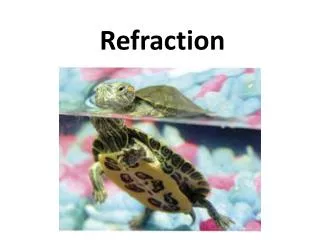

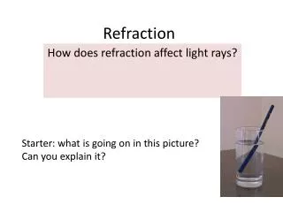
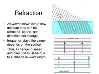
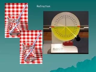
Refraction
E N D
Presentation Transcript
Glass block 35o Starter frequency speed wavelength When light passes from one medium to another its _________ does not change. What does change is its ______and this causes the __________ of light to change as well. When a ray of light passes from a denser medium to a less dense medium, the ray bends ___________ the normal. away from The absolute refractive index for some substances are given below. Snell’s law n1sinθ1 = n2 sinθ2 a.) The glass block shown on the right is immersed in water.Complete the ray diagram to show what happens to the ray of light as it emerges from the glass block nglass = 1.52 nwater = 1.33 nplastic= 1.45 (b) Use Snell’s law to calculate the angle of refraction at the first interface given the angle of incidence is 35o.
Glass block 35o Starter The absolute refractive index for some substances are given below. Snell’s law n1sinθ1 = n2 sinθ2 a.) The glass block shown on the right is immersed in water.Complete the ray diagram to show what happens to the ray of light as it emerges from the glass block nglass = 1.52 nwater = 1.33 nplastic= 1.45 More dense to less dense bends away from the normal (b) Use Snell’s law to calculate the angle of refraction at the first interface given the angle of incidence is 35o. sinθ2 = 0.5019 1.33 sin35° = 1.52 sinθ2 θ2 = sin -10.5019 1.33 sin35° = sinθ2 1.52 θ2 = 30.1°
Refraction from less dense to more dense Light bends towards the normal
Refraction from more dense to less dense Light bends awayfrom the normal
Refraction from more dense to less dense Wave bends awayfrom the normal, until it reaches the critical angle and total internal reflection occurs
Total Internal Reflection • Criteria: • light is passing from a dense to a less dense medium (eg. water to air) • critical angle of incidence is when the angle of refraction reaches 90° • if angle incidence > critical angle, all of the light is reflected Test it out!
Task: Determine the critical angle for perspex experimentally Compare this with the values calculated using Snell’s Law
nglass = 1.52 nwater = 1.33 nplastic= 1.45 Starter C1 = speed of light in a vacuum = 3.00 x 10⁸ ms-1 n = Calculate the speed of light, c2 in glass c2 = 8 = = 1.97 x10⁸ ms-1
water glass plastic 45o nglass = 1.52 nwater = 1.33 nplastic= 1.45 Starter A ray of light passes from water into plastic at 45o and then into glass as shown in the diagram. (a) Sketch the likely path of the ray considering the three refractive index values given. (b) Calculate the incident angle of the ray on the plastic-glass interface. θ2 First we must find the angle of refraction from water to plastic using Snell’s Law θ2 Alternate angles, parallel lines are equal 1.33 sin45° = 1.45 sinθ2 1.33 sin45° = sinθ2 1.45 θ2 = 40.4° Less dense to more dense bends towards the normal sinθ2 = 0.6486
Snell’s Law n1sinθ1 = n2sinθ2 nglass = 1.52 nwater = 1.33 nplastic= 1.45 Like Question 4 – pg 98 a.) It enters the prism at a right angle, therefore no refraction occurs. b.) Angle of incidence is Θ1 = 45° c.) Angle of refraction as light ray emerges is • n1sinθ1 = n2sinθ2 water 45° • 1.52 sin45 = 1.33 sinθ2 1.52 sin45° = sinθ2 1.33 θ1 Θ2 = 57.8° θ2 glass 45° 0.8463 = sinθ2
65o 40o 35o Total Internal Reflection When the angle of refraction is 90°, the incident angle is at the critical angle On the following three diagrams sketch what happens to the ray of light as it strikes the interface between the two media shown. The critical angle for this interface is 40o. 65o 40o 35o Total Internal Reflection At critical angle
Total Internal Reflection The absolute refractive index for 3 transparent substances are as follows: substance A = 1.10 substance B = 1.30 substance C = 1.55 When the angle of refraction is 90°, the incident angle is at the critical angle Calculate the critical angle for light passing from (a) Substance B to substance A. (using Snell’s Law) • 1.30 sinθ1 = 1.10 sin 90° Is it possible to calculate the critical angle from substance B to substance C? • sinθ1 = 1.10 / 1.30 • sinθ1 = 0.8462 No, ray is bending towards the normal because it is passing from a less dense substance to more dense substance • θ1 = 57.8°
Fiber Optics Long thin strands of pure glass about the diameter of a human hair. Arranged in bundles called optical cables, they are used to transmit infrared light (from LED’s) or laser light signals over long distances. The core is _______ dense than the cladding. more
How does it work? Total Internal Reflection! Light constantly bounces off the cladding due to total internal reflection. Some of the signal may degrade due to impurities in the glass Advantages:(compared to copper wire) Cheaper Low power Non flammable Higher carrying capacity Thinner Ideal for digital signals Lightweight Less signal degradation
sinθc = n2 / n1 (n1 is more dense > than n2) n2 n1 In fiber optics, the critical angle is described with respect to the parallel axis running down the middle of the fiber. Therefore, the fiber-optic critical angle = (90 degrees - physics critical angle).
Light reflects from the cladding no matter what angle the fiber itself gets bent at, even if it's a full circle!
Starter The speed of a wave train in a pool of water is 2ms-1. It passes over a shallow section of the pool in which its speed drops to 1.5 ms-1. The frequency of the waves remains the same at 10 Hz. (a) What is the wavelength of the waves in the deep water? (b) What is the refractive index of the interface between the deep and shallow water? v = fλ λ = λ = 0.2 m λ = n1 = v1 n2 v2 n = 1.33 n =
Dispersion A refractory phenomenon that occurs when light enters a denser transparent medium. It slows down proportional to its wavelength – splitting white light into its component colours ROYGBIV Violet light (higher frequency) refracts more than red light (lower frequency) shorter wavelength longer wavelength n = 1.51 n = 1.53
Huygen’s Principle Every point on a wave front is considered to be a source of tiny wavelets.
Plane Mirrors • Images in a plane mirror are: • virtual • upright • laterally inverted • the same size as the object • the same distance from the mirror as the object.
Plane Mirrors • Images in a plane mirror are: • virtual • upright • laterally inverted • the same size as the object • the same distance from • the mirror as the object.
Curved Mirrors Focal point Concave
Concave Mirrors Rays parallel to the principal axis will converge at the focal point Focal point Principal axis
Curved Mirrors Convex Focal point A convex mirror diverges the reflected light rays so the image appears behind the mirror
Ray Diagrams for Curved Mirrors R = radius of curvature f= focal length = ½ R R f Principal axis Centre of Curvature Focal Point Vertex (geometric centre)
Ray Diagrams for Curved Mirrors • Rays parallel to the principal axis are reflected through the focus (or as if they pass through the focus for convex).
Ray Diagrams for Curved Mirrors • Rays that pass through the focus are reflected parallel to the principal axis.
Ray Diagrams for Curved Mirrors • Rays that hit the pole of the mirror reflect with angle of reflection = angle of incidence.
Ray Diagrams for Curved Mirrors • Rays that pass through the centre of curvature are reflected along the same path.
Case 1: Object is further from the mirror from C Image is: real, inverted, diminished, between C and the mirror.
Case 2: Object is at C Image is: real, inverted, same size, at C.
Case 3: Object is between C and F Image is: real, inverted, enlarged, further from the mirror than C.
Case 4: Object is at F Image is: Image at infinity/no image.