Test Facility Capabilities EGSE
Test Facility Capabilities EGSE. EGSE overview. Router & Test Equipment Gateway. Router distributes PUS (Packet Utilisation Standard)TM & TC packets around the EGSE subsystems Test equipment gateway implements PUS handling for the test equipment controllers

Test Facility Capabilities EGSE
E N D
Presentation Transcript
Test Facility Capabilities EGSE Erich Wiezorrek, MPE
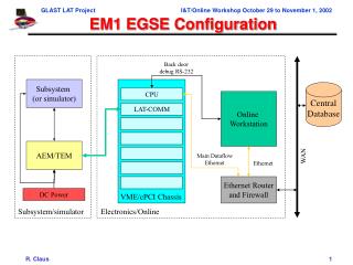
Erich Wiezorrek, MPE EGSE overview
Erich Wiezorrek, MPE Router & Test Equipment Gateway • Router • distributes PUS (Packet Utilisation Standard)TM & TC packets around the EGSE subsystems • Test equipment gateway • implements PUS handling for the test equipment controllers • distributes TC packets to the corresponding test equipment controller • collects all TM packets from the test equipment controllers
Erich Wiezorrek, MPE CDMS Simulator • implements MIL-STD-1553b communication bus to connect DPU and EGSE • transfers TM packets from DPU to EGSE • transfers TC packets from EGSE to DPU • synchronizes DPU time with its own time • allows selection of several user defined bus lists • no mission time line implemented; TCs for DPU are transferred immediately to DPU after they are received from EGSE
Erich Wiezorrek, MPE XY Stage Controller • allows positioning of external sources (hole mask) via TC • reports all moves via TM packets • for FM ILT also simple pointing rasters will be implemented • for FM ILT XY stage scans to support bolometer testing will be implemented
Erich Wiezorrek, MPE Test Optic Controller • both flip mirrors can be commanded via TC • to switch between internal and external calibration sources • to switch between internal integrating sphere and internal black bodies • chopper wheel can be commanded via TC to select one of the two internal black bodies • chopper wheel can be commanded via TC to rotate with a selectable frequency to regularly switch between the internal black bodies • periodic TM packets to report status • “event” TM packets whenever chopper wheel passes fixed hall sensors
Erich Wiezorrek, MPE Environment monitor & Stimuli control • regular HK TM reports from • several temperatures inside the cryostat • pressure of the cryostat and the gas cell • liquid level measurements for N2 and He • status, set point, actual temperature and heating power for both internal black bodies • set point for internal black bodies can be set via TC
Erich Wiezorrek, MPE HCSS Interface • TM packets together with decompressed dataframes will be stored in the HCSS database • Test procedures will call for predefined CUS observations • CUS generated TC sequences will be executed by the TestControl/TOPE system • “Data processing” users will be able to fetch data associated with a test execution or a CUS observation via a browser interface • OOL and TC history will be fetched from SCOS and ingested into the database