Mastering LCD Technology for Embedded Systems
430 likes | 494 Vues
Explore LCD internal components, usage guide, font customization, and commands for embedded systems. Learn about LCD pinout and functionality for efficient user communication.

Mastering LCD Technology for Embedded Systems
E N D
Presentation Transcript
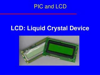
LCD and Keyboard Sepehr Naimi www.NicerLand.com
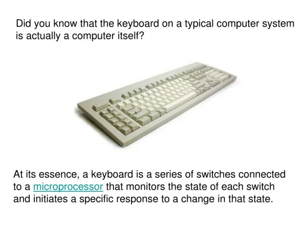
About LCD • Sometimes the embedded system needs to inform the user of something. There are different ways to inform the user, such as LEDs, 7segments and LCDs. • LCD is one of the most powerful ways; as you can display different texts and icons on it.
Topics: • LCD pin out • LCD internal components • How to use LCD • Busy • LCD commands • Changing fonts (case study) • additional references
LCD internal components CGRAM 40H 41H 42H 7EH 7FH Data Register ... Command Register DDRAM 80H 81H 82H FEH FFH Cursor ... • DDRAM (Data Display RAM) • CGRAM(Character Generator RAM) • Cursor (Address Counter) • Data Register • Command Register
DDRAM (Data Display RAM) DDRAM (Data Display RAM) It is a 128x8 RAM (128 bytes of RAM) Contains the data that should be displayed on the LCD. If we write the ASCII code of a character into the RAM the character will be displayed on the LCD. CGRAM (Character Generator RAM) It is a 64x8 RAM (64 bytes of RAM). The fonts of characters 00H to 07H are stored in the RAM. We can change the fonts of the 8 characters by writing into the RAM. Cursor (Address Counter) Cursor is a register which points to a location of DDRAM or CGRAM.
DDRAM (Data Display RAM) Data Register It is an 8 bit register. When we write a byte of data into the data register, the data will be written where the cursor points to. For example, if we write a byte of data into the data register while the cursor points to location 80H of DDRAM, the contents of location 80H will be changed to the data, we have written into the data register. Command Register We can command the LCD by writing into the command register. For example, we can ask the LCD, to set cursor location, or clean the screen, by writing into the command Register.
Writing to Data Register (Example) CGRAM 40H 41H 42H 7EH 7FH Data Register ... DDRAM 80H 81H 82H FEH FFH Cursor ... 50H Command Register P
LCD commands • We mentioned earlier that we can order the LCD by sending command codes to the command register. • Some of the command codes are listed in the following table.
Clear Display Screen • If we write 01H into the command register, LCD clears the display, and sets the cursor address to 0.
Display and Cursor • Display on cursor blinking (0FH) • Display on cursor on (0EH) Hello world ! Hello world ! • Display on cursor off (0CH) • Display off cursor off (0AH) Hello world !
Return home • If we write 02H into the command register, LCD sets the cursor address to 0. It also returns display to original position if being shifted.
Set cursor position (Set DDRAM address) • We mentioned earlier that each location of the DDRAM, retains the character that should be displayed in a location of LCD. • The following figures, represent that if you want to display a character in each of the rooms of the LCD, you should write into which location of the DDRAM. (The numbers are in hex.) • To move the cursor to any location of the DDRAM, write the address of that location into the command register. 1 2 3 … 18 19 20 Line 1 1 2 3 … 18 19 20 20x1 LCD Line 1 Line 2 Line 3 Line 4 1 2 3 … 18 19 20 Line 1 Line 2 20x4 LCD 20x2 LCD 1 2 3 … 38 39 40 1 2 3 … 14 15 16 Line 1 Line 2 Line 1 Line 2 40x2 LCD 16x2 LCD
Set cursor position (example) Solution: We should move cursor to address D4H of the DDRAM. So, we should write D4H, into the command register. • We want to display a character in line 4 column 1 of a 20x4 LCD. What should we write to the command register to move the cursor to? 1 2 3 … 18 19 20 Line 1 Line 2 Line 3 Line 4
Decrease and increase Cursor • If you write a byte of data into the data register, the data will be written where the cursor points to, and cursor will be incremented, by default. • If you want to make the LCD, to decrement the cursor, you should write 4H into the command register. • If you want to make the LCD, to reactivate the default (shift cursor to right) you should write 6H into the command register. Hello Hello Increment cursor Decrement cursor
LCD pins D7 D6 D5 D4 D3 D2 D1 D0 E RW VEE VCC VSS RS In this section, you learn the functionalities of the LCD pins.
LCD pins D7 D6 D5 D4 D3 D2 D1 D0 E RW VEE VCC VSS RS • VSS and VCC: These pins provide the energy to the LCD. We must connect them to +5V. + +5 -
LCD pins D7 D6 D5 D4 D3 D2 D1 D0 E RW VEE VCC VSS RS • VEE: We control the contrast of the LCD by giving a voltage between 0V and +5V to the pin. Hello world ! + +5 -
LCD pins D7 D6 D5 D4 D3 D2 D1 D0 E RW VEE VCC VSS RS • D0 to D7: LCD sends and receives data, through the 8 pins.
LCD pins D7 D6 D5 D4 D3 D2 D1 D0 E RW VEE VCC VSS RS • R/W (Read/Write): • When we want to send (write) data to the LCD, we make the pin, low. • When we want to receive (read) data from the LCD, we set the pin to high.
LCD pins D7 D6 D5 D4 D3 D2 D1 D0 E RW VEE VCC VSS RS E E • E (Enable): We activate the pin when we want to send or receive data from the LCD. • When we want to send data to the LCD, we make the RW pin, low; and supply the data to data pins (D0 to D7); and then apply a high to low pulse to the Enable pin. • When we want to receive data from the LCD, we make the RW pin, high; and then apply a low to high pulse to the Enable pin. LCD supplies data to the data pins (D0 to D7).
LCD pins Data Register D7 D6 D5 D4 D3 D2 D1 D0 E RW VEE VCC VSS RS • RS (Register select): There are two registers with names of command register and data register in the LCD. • If RS = 1, whenever we send data to the LCD, the data will be located in the data register. • If RS = 0, whenever we send data to the LCD, the data will be located in the command register RS 1 0 Command Register
LCD Programming • Initialization • We must initialize the LCD before we use it. • To initialize an LCD, for 5×7 matrix and 8-bit operation, 0x38, 0x0E, and 0x01 are send to the command register. • Sending commands to the LCD • Make pins RS and R/W = 0 • Put the command number on the data pins (D0–D7) • Send a high-to-low pulse to the E pin to enable the internal latch of the LCD (wait about 100us after each command) • Sending data to the LCD • make pins RS = 1 and R/W = 0. • put the data on the data pins (D0–D7) • send a high-to-low pulse to the E pin (wait about 100us)
An example D7 D6 D5 D4 D3 D2 D1 D0 E RW VEE VCC VSS RS • Write a program that displays ‘H’ on the LCD. Solution: PORTC |= (1<<5); // (RS = 1) to write to the data register PORTC &= (1<<4); // (RW = 0) to send data to the LCD. PORTD = ‘H’; // to send ‘H’ to the LCD. //To make a High to low pulse on the Enable pin : PORTC |= (1<<3); _delay_ms (1); PORTC &= ~(1<<3);
LCD Programming in 4-bit mode • To save pins of the AVR, we can use 4-bit operating mode. • The initialization of 4-bit mode is somehow different: • In 4-bit mode, we initialize the LCD with the series 33, 32, and 28 in hex. • This represents nibbles 3, 3, 3, and 2, which tells the LCD to go into 4-bit mode. The value $28 initializes the display for 5 × 7 matrix and 4-bit operation • Sending commands and data to the LCD • Sending data and commands to the LCD is like the 8-bit mode but we should only use D4 – D7 • First we should send the high nibble to D4-D7, then, to send the low nibble, swap the low nibble with the high nibble, and send it to D4-D7
Changing fonts (Changing CGRAM) D7 D6 D5 D4 D3 D2 D1 D0 • Each character LCD has a CGRAM (Character generator RAM). It stores the fonts of the first 8 characters (character 0H to character 7H). So, you can change the font of the 8 characters and define new characters, by writing into the CGRAM. Each byte of the CGRAM stores a row of a font. The fonts are stored respectively, in the CGRAM. For example, if you change the content of first byte of the CGRAM (whose address is 40H), you have changed the highest row of character 0H. • Attention: in an LCD with 5x7 font, each font has actually 8 rows. The 8th row is put aside for the cursor. You would better not set the bits of the 8th row. 40 41 42 43 44 45 46 47 48 49 4A 4B 4C 4D 4E 4F : : Character 0 Character 1 CGRAM (Its first 16 bytes)
Changing fonts • To change a row of a font, you should follow the following direction: • Set the cursor position to point to the location of the CGRAM that you want to change. • Change the font of the selected row, by writing into data register. • Attention: LCD has only one cursor. When you want to change the CGRAM you make it point to CGRAM and when you want to display something on the screen you make it point to a location of DDRAM. So, when you finished changing the fonts don’t forget to set the cursor position, so that, it points to DDRAM.
Setting CGRAM address • To make the cursor point to any location of CGRAM, or DDRAM, simply write the address of the location into the command register.
Setting CGRAM address (Example) • We want to change the font of the 4th row of character 01H. What should we write to the command register to make the cursor point to the relevant address. D7 D6 D5 D4 D3 D2 D1 D0 40 41 42 43 44 45 46 47 Character 0 • Solution: As you can see in the figure, the address of the 4th row of character 01H is 4BH. So, we should write 4BH into the command register. 48 49 4A 4B 4C 4D 4E 4F : : Character 1 CGRAM (Its first 16 bytes)
Bounce AVR VCC PB1 Time A key press may be considered as more than one click VPB1
Debouncing (The correct way of reading keys) do{ while((PINB&1) == 0); delay_ms (20); }while((PINB&1) == 0); do{ while((PINB&1) == 1); delay_ms (20); }while((PINB&1) == 1); A++;
Using Keyboard PB.6 PB.5 PB.4 PB.3 PB.7 PB.1 PB.0 PB.2 AVR If we connect each key to a pin of the AVR, we waste many pins. So we use scanning as shown in the next slide PC.0 PC.1 PC.2 PC.3 PC.4 PC.5 PC.6 PC.7
Keyboard 1 2 3 é 4 5 6 ç 7 8 9 è Cancel 0 OK ê VCC D3 D2 D1 D0 D3 D2 D1 D0
Creating a Matrix keyboard D3 D2 INPUT D1 D0 D3 D2 D1 D0 OUTPUT VCC
Connecting to AVR AVR PB5 PB4 PB3 PB2 PB1 PB0 PD7 PD6 PD5 PD4 PD3 PD2 PD1 PD0 PC0 PC1 PC2 PC3 PC4 PC5 VCC D3 D2 D1 D0 D3 D2 D1 D0
Keyboard Programming • Writing programs for Matrix Keyboard • Key press detection • Aim: detecting if any of the keys is pressed • Key identification (scanning the keyboard) • Aim: identifying that which of the keys is pressed
Press detection (is any of the keys pressed) VCC D3 D2 PORTC D1 D0 D3 D2 D1 D0 PORTB
Key identification VCC VCC VCC VCC D3 D2 D1 D0 D3 D2 D1 D0
Key identification VCC VCC VCC VCC D3 D2 D1 D0 D3 D2 D1 D0
Key identification VCC VCC VCC VCC D3 D2 D1 D0 D3 D2 D1 D0
Key identification VCC VCC VCC VCC D3 D2 D1 D0 D3 D2 D1 D0
Example 1 2 3 é 4 5 6 ç 7 8 9 è Cancel 0 OK ê • Write a function, that waits for a key to be pressed and then returns the code of the pressed key. D3 D2 D1 D0 D3 D2 D1 D0
Solution Start Ground next row Ground all rows Read all columns Read all columns Read all columns Any key down? Key press in this row No No All keys open? No Yes Yes Find which key is pressed Yes Wait for de-bounce Read all columns Get code from table Any key down? No Return Yes