Understanding the Network Layer: Routing, DHCP, NAT, and IPv6 Insights
This chapter delves into essential network layer concepts including routing principles, dynamic IP address allocation via DHCP, and NAT for efficient address management. It covers the fundamentals of IPv4 addressing and datagram transmission, illustrating how data is fragmented and managed within IP protocols. Additionally, it explores ICMP for error reporting and highlights IPv6 implementation as the future of internet addressing. Understanding these principles is crucial for efficient network design and management in our increasingly connected world.

Understanding the Network Layer: Routing, DHCP, NAT, and IPv6 Insights
E N D
Presentation Transcript
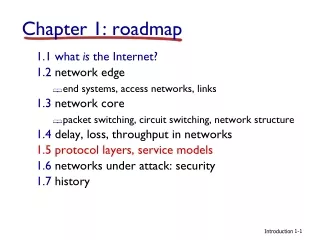
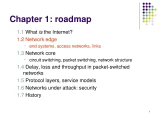
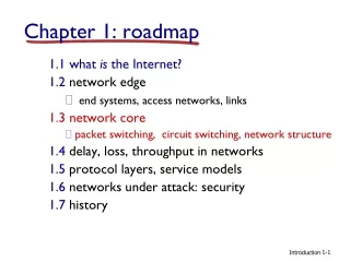
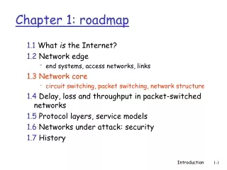
Chapter 4 roadmap 4.1 Introduction and Network Service Models 4.2 Routing Principles 4.3 Hierarchical Routing 4.4 The Internet (IP) Protocol • 4.4.1 IPv4 addressing • 4.4.2 Moving a datagram from source to destination • 4.4.3 Datagram format • 4.4.4 IP fragmentation • 4.4.5 ICMP: Internet Control Message Protocol • 4.4.6 DHCP: Dynamic Host Configuration Protocol • 4.4.7 NAT: Network Address Translation 4.5 Routing in the Internet 4.6 What’s Inside a Router 4.7 IPv6 4.8 Multicast Routing 4.9 Mobility Network Layer
used by hosts, routers, gateways to communication network-level information error reporting: unreachable host, network, port, protocol echo request/reply (used by ping) network-layer “above” IP: ICMP msgs carried in IP datagrams ICMP message: type, code plus first 8 bytes of IP datagram causing error ICMP: Internet Control Message Protocol TypeCodedescription 0 0 echo reply (ping) 3 0 dest. network unreachable 3 1 dest host unreachable 3 2 dest protocol unreachable 3 3 dest port unreachable 3 6 dest network unknown 3 7 dest host unknown 4 0 source quench (congestion control - not used) 8 0 echo request (ping) 9 0 route advertisement 10 0 router discovery 11 0 TTL expired 12 0 bad IP header Network Layer
DHCP: Dynamic Host Configuration Protocol Goal: allow host to dynamically obtain its IP address from network server when it joins network Can renew its lease on address in use Allows reuse of addresses (only hold address while connected an “on” Support for mobile users who want to join network (more shortly) DHCP overview: • host broadcasts “DHCP discover” msg • DHCP server responds with “DHCP offer” msg • host requests IP address: “DHCP request” msg • DHCP server sends address: “DHCP ack” msg Network Layer
E B A DHCP client-server scenario 223.1.2.1 DHCP 223.1.1.1 server 223.1.1.2 223.1.2.9 223.1.1.4 223.1.2.2 arriving DHCP client needs address in this network 223.1.1.3 223.1.3.27 223.1.3.2 223.1.3.1 Network Layer
DHCP discover src : 0.0.0.0, 68 dest.: 255.255.255.255,67 yiaddr: 0.0.0.0 transaction ID: 654 DHCP client-server scenario arriving client DHCP server: 223.1.2.5 DHCP offer src: 223.1.2.5, 67 dest: 255.255.255.255, 68 yiaddrr: 223.1.2.4 transaction ID: 654 Lifetime: 3600 secs DHCP request src: 0.0.0.0, 68 dest:: 255.255.255.255, 67 yiaddrr: 223.1.2.4 transaction ID: 655 Lifetime: 3600 secs time DHCP ACK src: 223.1.2.5, 67 dest: 255.255.255.255, 68 yiaddrr: 223.1.2.4 transaction ID: 655 Lifetime: 3600 secs Network Layer
NAT: Network Address Translation rest of Internet local network (e.g., home network) 10.0.0/24 10.0.0.1 10.0.0.4 10.0.0.2 138.76.29.7 10.0.0.3 Datagrams with source or destination in this network have 10.0.0/24 address for source, destination (as usual) All datagrams leaving local network have same single source NAT IP address: 138.76.29.7, different source port numbers Network Layer
NAT: Network Address Translation • Motivation: local network uses just one IP address as far as outside word is concerned: • no need to be allocated range of addresses from ISP: - just one IP address is used for all devices • can change addresses of devices in local network without notifying outside world • can change ISP without changing addresses of devices in local network • devices inside local net not explicitly addressable, visible by outside world (a security plus). Network Layer
NAT: Network Address Translation Implementation: NAT router must: • outgoing datagrams:replace (source IP address, port #) of every outgoing datagram to (NAT IP address, new port #) . . . remote clients/servers will respond using (NAT IP address, new port #) as destination addr. • remember (in NAT translation table) every (source IP address, port #) to (NAT IP address, new port #) translation pair • incoming datagrams:replace (NAT IP address, new port #) in dest fields of every incoming datagram with corresponding (source IP address, port #) stored in NAT table Network Layer
2 4 1 3 S: 138.76.29.7, 5001 D: 128.119.40.186, 80 S: 10.0.0.1, 3345 D: 128.119.40.186, 80 1: host 10.0.0.1 sends datagram to 128.119.40, 80 2: NAT router changes datagram source addr from 10.0.0.1, 3345 to 138.76.29.7, 5001, updates table S: 128.119.40.186, 80 D: 10.0.0.1, 3345 S: 128.119.40.186, 80 D: 138.76.29.7, 5001 NAT: Network Address Translation NAT translation table WAN side addr LAN side addr 138.76.29.7, 5001 10.0.0.1, 3345 …… …… 10.0.0.1 10.0.0.4 10.0.0.2 138.76.29.7 10.0.0.3 4: NAT router changes datagram dest addr from 138.76.29.7, 5001 to 10.0.0.1, 3345 3: Reply arrives dest. address: 138.76.29.7, 5001 Network Layer
NAT: Network Address Translation • 16-bit port-number field: • 60,000 simultaneous connections with a single LAN-side address! • NAT is controversial: • routers should only process up to layer 3 • violates end-to-end argument • NAT possibility must be taken into account by app designers, e.g., P2P applications • address shortage should instead be solved by IPv6 Network Layer
Chapter 4 roadmap 4.1 Introduction and Network Service Models 4.2 Routing Principles 4.3 Hierarchical Routing 4.4 The Internet (IP) Protocol 4.5 Routing in the Internet • 4.5.1 Intra-AS routing: RIP and OSPF • 4.5.2 Inter-AS routing: BGP 4.6 What’s Inside a Router? 4.7 IPv6 4.8 Multicast Routing 4.9 Mobility Network Layer
Routing in the Internet • The Global Internet consists of Autonomous Systems (AS) interconnected with each other: • Stub AS: small corporation: one connection to other AS’s • Multihomed AS: large corporation (no transit): multiple connections to other AS’s • Transit AS: provider, hooking many AS’s together • Two-level routing: • Intra-AS: administrator responsible for choice of routing algorithm within network • Inter-AS: unique standard for inter-AS routing: BGP Network Layer
Internet AS Hierarchy Intra-AS border (exterior gateway) routers Inter-ASinterior (gateway) routers Network Layer
Intra-AS Routing • Also known as Interior Gateway Protocols (IGP) • Most common Intra-AS routing protocols: • RIP: Routing Information Protocol • OSPF: Open Shortest Path First • IGRP: Interior Gateway Routing Protocol (Cisco proprietary) Network Layer
RIP ( Routing Information Protocol) • Distance vector algorithm • Included in BSD-UNIX Distribution in 1982 • Distance metric: # of hops (max = 15 hops) • Can you guess why? • Distance vectors: exchanged among neighbors every 30 sec via Response Message (also called advertisement) • Each advertisement: list of up to 25 destination nets within AS Network Layer
RIP: Example z w x y A D B C Destination Network Next Router Num. of hops to dest. w A 2 y B 2 z B 7 x -- 1 …. …. .... Routing table in D Network Layer
z w x y A D B C RIP: Example Dest Next hops w - - x - - z C 4 …. … ... Advertisement from A to D Destination Network Next Router Num. of hops to dest. w A 2 y B 2 z B A 7 5 x -- 1 …. …. .... Routing table in D Network Layer
RIP: Link Failure and Recovery If no advertisement heard after 180 sec --> neighbor/link declared dead • routes via neighbor invalidated • new advertisements sent to neighbors • neighbors in turn send out new advertisements (if tables changed) • link failure info quickly propagates to entire net • poison reverse used to prevent ping-pong loops (infinite distance = 16 hops) Network Layer
routed routed RIP Table processing • RIP routing tables managed by application-level process called route-d (daemon) • advertisements sent in UDP packets, periodically repeated Transprt (UDP) Transprt (UDP) network forwarding (IP) table network (IP) forwarding table link link physical physical Network Layer
RIP Table example (continued) Router: giroflee.eurocom.fr Destination Gateway Flags Ref Use Interface -------------------- -------------------- ----- ----- ------ --------- 127.0.0.1 127.0.0.1 UH 0 26492 lo0 192.168.2. 192.168.2.5 U 2 13 fa0 193.55.114. 193.55.114.6 U 3 58503 le0 192.168.3. 192.168.3.5 U 2 25 qaa0 224.0.0.0 193.55.114.6 U 3 0 le0 default 193.55.114.129 UG 0 143454 • Three attached class C networks (LANs) • Router only knows routes to attached LANs • Default router used to “go up” • Route multicast address: 224.0.0.0 • Loopback interface (for debugging) Network Layer
OSPF (Open Shortest Path First) • “open”: publicly available • Uses Link State algorithm • LS packet dissemination • Topology map at each node • Route computation using Dijkstra’s algorithm • OSPF advertisement carries one entry per neighbor router • Advertisements disseminated to entire AS (via flooding) • Carried in OSPF messages directly over IP (rather than TCP or UDP Network Layer
OSPF “advanced” features (not in RIP) • Security: all OSPF messages authenticated (to prevent malicious intrusion) • Multiple same-cost paths allowed (only one path in RIP) • For each link, multiple cost metrics for different TOS (e.g., satellite link cost set “low” for best effort; high for real time) • Integrated uni- and multicast support: • Multicast OSPF (MOSPF) uses same topology data base as OSPF • Hierarchical OSPF in large domains. Network Layer
Hierarchical OSPF Network Layer
Hierarchical OSPF • Two-level hierarchy: local area, backbone. • Link-state advertisements only in area • each nodes has detailed area topology; only know direction (shortest path) to nets in other areas. • Area border routers:“summarize” distances to nets in own area, advertise to other Area Border routers. • Backbone routers: run OSPF routing limited to backbone. • Boundary routers: connect to other AS’s. Network Layer
Inter-AS routing in the Internet: BGP Network Layer
Internet inter-AS routing: BGP • BGP (Border Gateway Protocol):the de facto standard • Path Vector protocol: • similar to Distance Vector protocol • each Border Gateway broadcast to neighbors (peers) entire path (i.e., sequence of AS’s) to destination • BGP routes to networks (ASs), not individual hosts • E.g., Gateway X may send its path to dest. Z: Path (X,Z) = X,Y1,Y2,Y3,…,Z Network Layer
Internet inter-AS routing: BGP Suppose: gateway X send its path to peer gateway W • W may or may not select path offered by X • cost, policy (don’t route via competitors AS), loop prevention reasons. • If W selects path advertised by X, then: Path (W,Z) = w, Path (X,Z) • Note: X can control incoming traffic by controlling it route advertisements to peers: • e.g., don’t want to route traffic to Z -> don’t advertise any routes to Z Network Layer
BGP: controlling who routes to you • A,B,C are provider networks • X,W,Y are customer (of provider networks) • X is dual-homed: attached to two networks • X does not want to route from B via X to C • .. so X will not advertise to B a route to C Network Layer
BGP: controlling who routes to you • A advertises to B the path AW • B advertises to X the path BAW • Should B advertise to C the path BAW? • No way! B gets no “revenue” for routing CBAW since neither W nor C are B’s customers • B wants to force C to route to w via A • B wants to route only to/from its customers! Network Layer
BGP operation Q: What does a BGP router do? • Receiving and filtering route advertisements from directly attached neighbor(s). • Route selection. • To route to destination X, which path )of several advertised) will be taken? • Sending route advertisements to neighbors. Network Layer
BGP messages • BGP messages exchanged using TCP. • BGP messages: • OPEN: opens TCP connection to peer and authenticates sender • UPDATE: advertises new path (or withdraws old) • KEEPALIVE keeps connection alive in absence of UPDATES; also ACKs OPEN request • NOTIFICATION: reports errors in previous msg; also used to close connection Network Layer
Why different Intra- and Inter-AS routing ? Policy: • Inter-AS: admin wants control over how its traffic routed, who routes through its net. • Intra-AS: single admin, so no policy decisions needed Scale: • hierarchical routing saves table size, reduced update traffic Performance: • Intra-AS: can focus on performance • Inter-AS: policy may dominate over performance Network Layer