Download
1 / 16
160 likes | 314 Vues
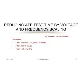
Reducing Test Time of Power Constrained Test by Optimal Selection of Supply Voltage. Praveen Venkataramani pzv0006@auburn.edu Vishwani D. AgrawaL vagrawal@eng.auburn.edu Auburn University, Dept. of ECE Auburn, AL 36849, USA

E N D
Reducing Test Time of Power Constrained Test by Optimal Selection of Supply Voltage Praveen Venkataramani pzv0006@auburn.edu Vishwani D. AgrawaL vagrawal@eng.auburn.edu Auburn University, Dept. of ECE Auburn, AL 36849, USA 26th International Conference on VLSI Design Pune, India, January 7, 2013
Outline Introduction Problem statement Effects of reducing power supply Power and structure constrained tests Analyzing power constrained test Analyzing structure constrained test Finding an optimum test voltage Results Conclusion VLSI Design"2012
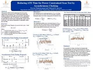
Introduction • Signal transitions of scan ATPG patterns arehigher than those of functional patterns • Cause high power dissipation during scan shift and capture • Peak power dissipation - IR drop failures • Average power dissipation – Excessive heating • Power Constraint Test • Limit the maximum scan test cycle power to the allowable peak power • Slow down clock • Generate or modify vector and scan structure to reduce activity • Increased test time VLSI Design"2012
Problem Statement • Limit maximum test power to the allowable peak power • Reduce scan test time • Proposed methodology • Reduce supply voltage to reduce power dissipation during test • Increase test clock frequency such that power dissipation meets the specification • Find the optimum voltage that allows the maximum power-constrained clock frequency for test VLSI Design"2012
Reducing Supply Voltage • Advantages • Reduced test time • Certain defects are more profound at lowervoltages • Resistive bridge fault • Power supply noise reduces • Concerns to be investigated in the future • Increased the critical path delay • Possible changes in critical paths VLSI Design"2012
Power and Structure Constrained Tests • Power Constraint • Scan based test power dissipation can be more than functional power dissipation • The maximum power dissipated by the test is limited by the maximum allowable power for the test. • Maximum activity test cycledetermines the test clock frequency • Structure Constraint • Clock frequency is determined by the critical path delay • Fastest test/functional clock period cannot be smaller than the critical path delay to avoid timing violation • Test at lower voltages tends to becomestructure constrained • Trade Off • Slower clock ⇒ Less power ⇒ Longer test time • Faster clock ⇒ Higher power ⇒ Shorter test time VLSI Design"2012
Power and Structure Constrained Tests Courtesy: ITC Elevator Talk Reduced Voltage Test Can be Faster! by Vishwani Agrawal VLSI Design"2012
Analysis of Power constrained test • The minimum test clock period for a set of ATPG test clock cyclesis limited by the maximum allowable power • Quantitatively : where TPOWER is the power constrained test clock period, EMAXtest is the maximum energy dissipated by the test PMAXfunc is the maximum allowable power • TPOWER is a function of voltage • Now, the total test time is then given by where , is the number of clock cycles. VLSI Design"2012
Analysis of Power constrained test VLSI Design"2012
Analysis of Structure Constrained Test • Critical path delay of a circuit can be approximated using α-power law model Where TSTRUCTURE is the critical path delay of the CUT VDD is the supply voltage VTH is the threshold voltage K is the proportionality constant dependent on the critical path α is the velocity saturation index • Decrease in VDDincreases delay • Total test time is given by VLSI Design"2012
Analysis of Structure Constrained Test • Assumptions: • Critical path does not change as voltage is reduced; found valid for small voltage changes • Threshold voltage remains constant VLSI Design"2012
Analysis of Structure Constrained Test VLSI Design"2012
Optimum Test Time • Putting it all together • Test time for power constrained test can be reduced by reducing the supply voltage • Critical path delay increases with reduction in supply voltage • Optimum test time for power constrained test isthe point at which the test clock runs fastest while the operation is still power constrained; • Power and structure-constrained test times are obtained analytically • Cross point gives the optimum voltage and test time, VLSI Design"2012
Optimum Test Time VLSI Design"2012
Results: Test Time Optimization VLSI Design"2012
Conclusion • What we have achieved • Optimum test time for power constrained test • Optimum voltage and frequency for power constrained tests • Future explorations • Consideration of separate critical paths for scan and functional logic • Delay testing at reduced voltage • Adaptive dynamic power supply • Dynamic test frequency (asynchronous testing) VLSI Design"2012