Download
1 / 56
560 likes | 713 Vues
High-resolution optical wave-front sensing and control. Eric W. Justh, P. S. Krishnaprasad. Institute for Systems Research University of Maryland, College Park Mikhail Vorontsov, Gary Carhart, Leonid Beresnev Intelligent Optics Laboratory

E N D
High-resolution optical wave-front sensing and control Eric W. Justh, P. S. Krishnaprasad Institute for Systems Research University of Maryland, College Park Mikhail Vorontsov, Gary Carhart, Leonid Beresnev Intelligent Optics Laboratory U.S. Army Research Laboratory, Adelphi, MD ----------------------- Presentation by PSK to Dr. Randy Zachery, ARO Harvard University, May 25, 2004 ------------- Other Collaborators: Ralph Etienne-Cummings, Viktor Gruev The Johns Hopkins University, Baltimore, MD
Outline • Background • - Adaptive optics: imaging through atmospheric turbulence • - Spatial Light Modulator (SLM) technology • - Phase-contrast technique for wave-front sensing • Applications for high-resolution wave-front control • Phase-contrast wave-front sensing using modern SLM technology • - Simple mathematical modeling • - Experimental results • High-resolution wave-front control system • - Block diagram • - Careful mathematical modeling • - Advantages over conventional approaches • Overview of experimental and simulation work at ARL • Analytical results
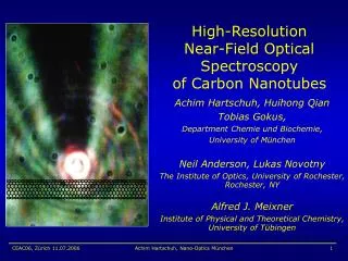
Imaging through turbulence T.E. Bell, “Electronics and the stars,” IEEE Spectrum, pp. 16-24, Aug. 1995.
Astronomical telescope mirror array T.E. Bell, “Electronics and the stars,” IEEE Spectrum, pp. 16-24, Aug. 1995.
Correction of vibrations and turbulence • Structural vibrations compensated primarily by large segmented mirror • - Tens to hundreds of large mirror segments (order of a meter across) • - Low frequency motion and correction (order of Hz) • - Large displacements needed (>>) • - High positioning accuracy (</2) • Atmospheric turbulence compensated by small deformable mirror • - Tens to hundreds of piezoelectric actuators • (mm to cm spacing) • - Higher frequency correction (hundreds of Hz) • - Modest displacements possible (several ) • - Higher positioning accuracy (<< )
Texas Instruments Micromirror Array • 106 mirrors on a 25mm 21mm chip (17m pitch) • +/- 10 degree tilts (digital on/off) • Time response of mirrors about 10s • Developed for displays rather than adaptive optics ant leg L.J. Hornbeck, “From cathode rays to digital micromirrors: A history of electronic projection display technology,” TI Technical Journal, pp. 7-46, July-Sept. 1998. (Figures from TI web site)
High-resolution SLMs for adaptive optics Pixelized devices: Boston University micromirror array (Developed by Tom Bifano’s group.) Continuous device: Pixelized liquid-crystal SLM Army Research Lab liquid crystal light valve (Leonid Beresnev of Mikhail Vorontsov’s group) (Pixelized LC SLM figures from University of Edinburgh website)
Pioneers Horace W. Babcock 1912-2003 Vladimir P. Linnik 1889-1984 Frits Zernike 1888-1966
H. W. Babcock (1953). “The possibility of compensating astronomical seeing”, Publications of the Astronomical Society of the Pacific, 65(386):229-236. F. Zernike (1955). “How I discovered phase contrast”, Science, 121: 345-349. (Discusses his original 1935 discovery in the context of developments in microscopy for which he received the 1953 Nobel Prize in Physics. This is the paper based on his acceptance speech.) H. W. Babcock (1990). “Adaptive optics revisited”, Science, 249(4996):253-257. References
Work at University of Maryland Ties to work at Boston University Ties to work at Harvard University Executive Summary
Accomplishments • Adaptive Optics • - Proof-of-concept experimental demonstration of the liquid crystal light valve (LCLV)-based high resolution wave-front control system (nonlinear Zernike filter realization) • - Simulation results show effectiveness against atmospheric turbulence • - Global nonlinear stability analysis for the continuous system model of the wave-front control system • - Patent disclosure (PS-2001-078) jointly to University of Maryland and Army Research Laboratory: Wave-front phase sensors based on optically or electrically controlled phase spatial light modulators for wave-front sensing and control (M.A. Vorontsov, E. W. Justh, L. Beresnev, P. S. Krishnaprasad, J. Ricklin)
From nonlinear Zernike filters to high-resolution adaptive optics
Micromachined deformable mirrors for adaptive optics Application: Optical systems used for communication, tracking, and imaging Problem: Aberrations in the beam path degrade performance substantially, particularly in horizontal beam paths. Higher resolution and better beam control are possible through active control using advanced wavefront compensation Solution: In a continuing collaboration, CDCSS researchers at Boston University and ARL researchers (M. Vorontsov) combined their respective technologies for Micromachined deformable mirrors (DMs) and advanced adaptive control to explore ultra-high resolution wavefront control. Recent Highlights: A point-to-point laser communication test bed at ARL, incorporating a BU 140 actuator DM and controlled through a stochastic gradient descent algorithm, allowed unprecedented control over a 2.5 km horizontal path.
Electrostatic Control of Interfaces • Initial motivation from Adaptive Optics for telescopes • High speed electrostatic control of fluid-fluid interfaces • Issues include • speed of response, • controllability of the interface, • stability of the fluid-fluid interface, • optimal dimensions and scale, • reflectivity • Demonstrate the practicality of optical switching under 1ms • Develop theory for determining performance limitations • This ideas are the subject of a patent issued in 2002.
Design of Switching Element Side View Top View • Self assembly of liquid-gas interface
Close Up of Fluid Switch Two switches
Babcock’s System • First paper on adaptive optics • The Eidophor was an early SLM based on charging an oil film with an electron gun. • The Eidophor technology had been developed during the late 1930s and 1940s as a projection display technology. deposited charge oil mirror H.W. Babcock, “The possibility of compensating atmospheric seeing,” Publ. Astron. Soc. Pacific., 65(386): 229-236, 1953. (Image from Olivier Lai’s view graphs on adaptive optics)
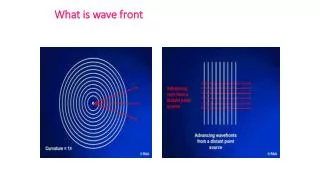
Zernike’s phase-contrast technique • Coherent optical waves have an intensity distribution (what is measured by a camera) and a phase distribution (which cannot be directly measured). • In 1935 Frits Zernike, a professor at the University of Groningen in the Netherlands, realized that the phenomenon of optical diffraction makes it possible to produce an intensity image which is related to the phase distribution of the wave. • For small phase deviations, a linear phase image is produced. • Zernike invented the phase-contrast microscope, based on his phase-imaging technique. • - Advantage: can image living transparent biological specimens. • - Before WWII, Zernike tried, but failed, to convince microscopists of the value of his ideas. • - It was discovered after WWII that the Germans had actively developed Zernike’s invention • Nobel Prize in Physics awarded to Zernike in 1953. F. Zernike, “How I Discovered Phase Contrast,” Science, 121: 345-349, 1955.
Phase-contrast sensing and astronomy • Papers by Dicke and Hardy examined Zernike’s phase-contrast technique in the context of wave-front sensing for astronomy: • [1] R.H. Dicke, “Phase-contrast detection of telescope seeing errors and their correction,” The Astrophysical Journal, 198: 605-615, 1975. • [2] J.W. Hardy, “Active Optics: A New Technology for the Control of Light,” Proceedings of the IEEE, 66(6): 651-697, 1978. • Linear analysis techniques are used, which are only applicable for small phase deviations. • Practical difficulties with phase-contrast sensing have precluded its use to date in adaptive optics for astronomy.
Laser guide star techniques • Idea: use back-scattering of pulsed laser light by molecules or atoms in the atmosphere (e.g., sodium atoms at an altitude of 90km) to measure the wave-front distortion due to atmospheric turbulence. • - For bright objects, a laser guide star is unnecessary. • - For dim objects near bright objects, the bright object serves as a natural guide star (hence the terminology “guide star”). • - At visible wavelengths, natural guide stars are only available for a very small percentage of the sky (<1% at =2.2µm). • From its invention in 1981 until 1992, laser guide star techniques were classified by the U.S. Government. • Freeman Dyson on the wall of secrecy surrounding SDI: “This action set back progress in the field of adaptive optics by ten years. The programs inside the wall of secrecy achieved little, and programs outside were discouraged. As often happens when secrecy is imposed on a government program, secrecy hides failures and exaggerates successes.”
Applications for high-resolution wave-front control • Atmospheric turbulence compensation • - Laser communications • - Laser polling of remote sensors • - Laser radar • - Directed laser energy applications (Airborne Laser) • - Astronomy • Atmospheric turbulence monitoring (potential application) • - Study fluid-flow around aircraft surfaces • - Sensor for active control of aircraft surfaces • Imaging transparent specimens (phase-contrast microscope) • - Biology • - Medicine • Correcting for phase distortion in optical system components
Phase-contrast technique of Zernike • Conventional Zernike filter phase-contrast sensor (Frits Zernike, 1935): Ain(r,t)=A0exp[i(r)] Iout(r) Lens Lens Distorted wave front Zernike phase plate Output intensity • The Zernike phase-plate phase-shifts the zero-order Fourier component (ideally by /2) relative to the rest of the spectrum, producing an image analogous to that of an interferometer: • Iout(r) = I0(r) + (2F)2IF(0) - 4FI0(r) IF(0) [cos((r) - ) - sin ((r) - ) ].
Conventional Zernike Filter Principle of Operation Glass slide with phase-shifting dot Aexp(iu(x,y)) camera O x z y f f f f • The complex envelope of the input wave is Aexp(iu(x,y)),where A is auniform intensity (over the beam cross-section), and u(x,y) is the phase distribution. • The left lens performs a spatial Fourier transform of the input wave. • The perfectly centered phase-shifting dot on the glass slide phase-shifts the zero-order spectral component relative to the rest of the spectrum. • The right lens performs the inverse Fourier transform. • The camera records the intensity distribution of the resulting optical signal 2 O O
Conventional Zernike Filter Response Function • The intensity at the camera is • The linearization of f around u (x,y)0 (and with the assumption that u(x,y) has zero mean, which involves no loss of generality) is • The conventional Zernike filter thus produces an output signal that is a direct measure of the wavefront of the input beam. f (u) = 2A (cos - 1)[P cos u + Q sin u - (P + Q )] + 2A sin (P sin u - Q cos u) + A P = cos udxdy, Q = sin udxdy, 2 2 2 O 2 2 O O where is the phase shift of the zero-order spectral component. O f (u) = (2A sin ) u. 2 O
Conventional Zernike Filter Strengths and Weaknesses • Strengths • Weaknesses • Unlike an interferometer, no reference beam is required • Directly measures wavefront, instead of wavefront slope (as in a Shack-Hartmann sensor or a shearing interferometer) • The conventional Zernike filter is highly sensitive to wavefront tilts and misalignment of optical components. • When wavefront variation is large, not much of the optical power is phase-shifted by the phase-shifting dot, and image contrast suffers.
Advanced phase-contrast sensor references V.Yu. Ivanov, V.P. Sivokon, and M.A. Vorontsov, “Phase retrieval from a set of intensity measurements: theory and experiment,” J. Opt. Soc. Am. A, Vol. 9, No. 9, pp. 1515-1524, 1992. J. Glückstad and P.C. Mogensen, “Analysis of wavefront sensing using a common path interferometer architecture,” Proc. 2nd International Workshop on Adaptive Optics for Industry and Medicine, pp. 241-246, 1999. J. Glückstad and P.C. Mogensen, “Reconfigurable ternary-phase array illuminator based on the generalized phase contrast method,” Optics Communications, Vol. 173, pp. 169-175, 2000. P.C. Mogensen and J. Glückstad, “Phase-only optical encryption,” Optics Letters, Vol. 25, No. 8, pp. 566-568, 2000. J. Glückstad, L. Lading, H. Toyoda, and T. Hara, “Lossless light projection,” Optics Letters, Vol. 22, No. 18, pp. 1373-1375, 1997. J. Glückstad, “Adaptive array illumination and structured light generated by spatial zero-order self-phase modulation in a Kerr medium,” Optics Communications, Vol. 120, pp. 194-203, 1995. A. Seward, F. Lacombe, and M. K. Giles, “Focal plane masks in adaptive optics systems,” SPIE Proceedings, Vol. 3762, pp. 283-293, July 1999.
LCLV-based nonlinear Zernike filter Liquid crystal light valve • LCLV fabricated in-house at ARL • LCLV acts as a high-resolution optically-controlled phase SLM • Intensity-to-phase-shift gain controlled electronically • Phase-shifts Fourier components in proportion to their power: robust to tilts M.A. Vorontsov, E.W. Justh, and L.A. Beresnev, JOSA A, 2001
Nonlinear Zernike filter experimental results 127-element liquid-crystal phase SLM (Meadowlark Optics HEX127) 4 displacement of central electrode of a (Xintics) deformable mirror Snapshot of atmospheric turbulence from a space heater with fan M.A. Vorontsov, E.W. Justh, and L.A. Beresnev, JOSA A, 2001
Generic high-resolution adaptive optic system Ain(r,t) Distorted wave front Corrected wave front Lens Pinhole Beam splitter IF(q=0,t) Acor(r,t) Beam splitter High-resolution SLM (wave-front corrector) Performance metric Wave-front sensor Camera Iout(r,t) Computes the next wave-front corrector image based on the image from the wave-front sensor
Complex envelope representation • Monochromatic light beam is an oscillatory field on space: use a complex envelope to describe a single component of electric or magnetic field. • Plane wave: • Polar form: • Drop z dependence (fix at z0) • Care about how phase field evolves and is controlled at a point z0 on optical axis • Time dependence in phase field introduced corresponding to quasi-static changes in complex envelope (e.g. turbulence, control action); not the time scale of electromagnetic field oscillations.
Continuous system model • Fourier series representation • Wave-front sensor image • Dynamics
Gradient dynamics property • The dynamics are (formally) gradient with respect to the energy functional • i.e., • Power coalesces in the Fourier modes being phase-shifted by the Fourier filter. • Changing the Fourier filter at discrete time instants yields a piecewise gradient flow. • We would like to have a Fourier-domain intensity-to-phase-shift mapping, computable in a parallel, distributed fashion (i.e., in real time), that produces a piecewise gradient flow leading ultimately to all the energy being concentrated in the zero-order Fourier component.
Strehl ratio • Phase-correcting SLM adds u(r,t) to the phase of the distorted input beam. • Strehl ratio is a natural normalized measure of phase distortion. • Ratio of the zero-order Fourier component intensity to the corresponding intensity in the absence of phase distortion. • See also: M.C. Roggemann, B.M. Welsh, and R.Q. Fugate, 1997, “Improving the resolution of ground-based telescopes,” Reviews of Modern Physics69(2): 437-505. M.C. Roggemann and B.M. Welsh, Imaging Through Turbulence, CRC Press, Boca Raton, 1996.
High-speed, high-resolution adaptive optic system Ain(r,t) Distorted wave front Corrected wave front Lens Pinhole Beam splitter IF(q=0,t) Acor(r,t) Beam splitter High-resolution SLM (wave-front corrector) Performance metric Wave-front sensor Parallel electronic interface Camera Iout(r,t)
Opto-electronically controlled spatial Fourier filter Implements Fourier filter operator
Mathematical modeling • Nonlinearity plays an essential role. • The key to successfully analyzing these feedback systems is to use models of the relevant optical physics which have sufficient fidelity, and yet are simple enough to yield qualitative insights. • Because the beam has a finite cross-section, there is no loss of information in using a two-dimensional Fourier series representation, as long as the Fourier domain-resolution is sufficiently high (to avoid aliasing). | |1/ Spatial domain Fourier (spatial frequency) domain
Fourier filter model • Fourier series representation • Wave-front sensor image
Fourier filter operators Fourier-domain intensity image Alternating Fourier phase filters
Nonlinear Zernike Filter Feedback System Fourier spectrum of corrected wave Zernike filter output intensity Distorted wave front produced by a 127-element liquid-crystal SLM (Meadowlark Optics HEX127) Phase-correcting SLM is an identical 127-element liquid-crystal SLM Feedback algorithm: integrate Iout with respect to time and feed back to SLM1 E.W. Justh, M.A. Vorontsov, G.W. Carhart, L.A. Beresnev, and P.S. Krishnaprasad, JOSA A, 2001
Feedback system experimental results Interferometer measurement of phase after correction (for 34 iterations) Interferometer measurement of initial phase distortion Spectrum after correction (Strehl ratio is improved by a factor of 8) Spectrum before correction E.W. Justh, M.A. Vorontsov, G.W. Carhart, L.A. Beresnev, and P.S. Krishnaprasad, JOSA A, 2001
Simulation results for atmospheric turbulence Phase profile =.23 =.41 =2.45 Phase distortion (sensor image) I=.35 I=.64 Distortion suppression (N = number of iterations) Intensity distortion E.W. Justh, M.A. Vorontsov, G.W. Carhart, L.A. Beresnev, and P.S. Krishnaprasad, JOSA A, 2001
High-resolution wave-front control system Corrected wave front Distorted wave front Wave-front sensor High-resolution SLM (Fourier filter) High-resolution SLM (wave-front corrector) Fourier-domain imager Wave-front sensor imager Parallel electronic interface Parallel electronic interface
Main result: gradient dynamics • Diffusion ensures existence and uniqueness of weak solutions: • Proposition: For (*) with • f corresponding to a common phase shift of an arbitrary (finite) collection I of Fourier components (0 < < ) • sufficiently large; • u(r,0), Du(r,0), (r), D(r) L2(); • periodic boundary conditions; • |a(r)|2dr is bounded; • if we let • then . (*) E.W. Justh, P.S. Krishnaprasad, and M.A. Vorontsov, Proc.CDC, 2000
Gradient dynamics property • With no diffusion, the energy functional becomes • and formally we have • Power coalesces in the Fourier modes being phase-shifted by the Fourier filter. • We try to understand the behavior of the system with a changing Fourier filter based on the analysis for fixed Fourier filters. • We would like to have a Fourier filter operator which is computable in real time, and which leads ultimately to all the energy being concentrated in the zero-order Fourier component.
Design problem formulation • Correcting for the distortion induced in an optical wave front due to propagation through a turbulent atmosphere can be formulated as a problem of automatic control. • General problem formulation: Subject to constraints of realizability, how can atmospheric turbulence compensation be performed optimally, given stochastic models for the wave-front distortion and photodetector noise? • Weaker problem formulation: Subject to constraints of realizability, how can atmospheric turbulence compensation be performed nearly optimally when the residual distortion is small, and adequately when the residual distortion is large, given simplified stochastic models for the wave-front distortion and photodetector noise?
Design problem • Given our basic system architecture, the design problem consists of: • - Choosing the Fourier filter operator • - Choosing feedback gain distribution • Design objectives: • - In the large-distortion (highly nonlinear) regime, the system remains nonlinearly stable and evolves toward the low-distortion (linear) regime. • - Requires judicious choice of Fourier filter operator • - Feedback gain limited by stability requirement • - In the low-distortion (linear) regime, • - Fourier filter operator has converged to a single-pixel Fourier filter • - Feedback gains depend on the turbulence, noise, and residual wave- front correction error statistics