Understanding DC and Stepper Motors: Mechanisms and Control Techniques
This guide provides an overview of DC motors and stepper motors, explaining their components and operational principles. Learn about the stationary stator and rotating rotor in DC motors, along with the limitations of brushes. Explore brushless DC motors and their benefits, including electronic control without a commutator. Understand full and half-step operations in stepper motors, their stepping patterns, and resolution differences. Discover H-Bridge control for motor directionality using microcontrollers and get insights into relevant driver chips.

Understanding DC and Stepper Motors: Mechanisms and Control Techniques
E N D
Presentation Transcript
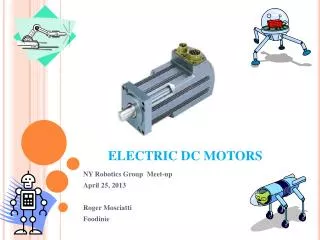
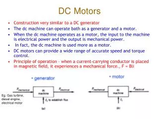
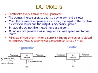
DC Motors • The stator is the stationary outside part of a motor. The rotor is the inner part which rotates. • Just as the rotor reaches alignment, the brushes move across the commutator contacts and energize the next winding • The brushes of a dc motor have several limitations; brush life, brush residue, maximum speed, and electrical noise
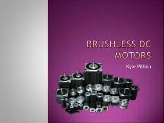
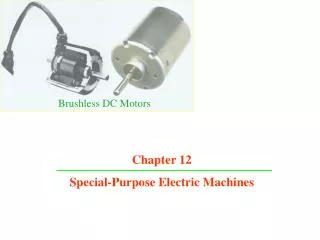
Brushless DC Motors • A brushless dc motor has a rotor with permanent magnets and a stator with windings. It is essentially a dc motor turned inside out. The control electronics replace the function of the commutator and energize the proper winding.
Full Stepper Motor • This animation demonstrates the principle for a stepper motor using full step commutation. The rotor of a permanent magnet stepper motor consists of permanent magnets and the stator has two pairs of windings. Just as the rotor aligns with one of the stator poles, the second phase is energized. The two phases alternate on and off and also reverse polarity. There are four steps. One phase lags the other phase by one step. This is equivalent to one forth of an electrical cycle or 90°.
Half Stepper Motor • This animation shows the stepping pattern for a half-step stepper motor. The commutation sequence for a half-step stepper motor has eight steps instead of four. The main difference is that the second phase is turned on before the first phase is turned off. Thus, sometimes both phases are energized at the same time. During the half-steps the rotor is held in between the two full-step positions. A half-step motor has twice the resolution of a full step motor. It is very popular for this reason.
Stepper Motors • Some stepper motor uses permanent magnets. Some stepper motors do not have magnets and instead use the basic principles of a switched reluctance motor. The stator is similar but the rotor is composed of a iron laminates.
Half Stepping • Note how the phases are driven so that the rotor takes half steps
Full Stepping • Animation shows how coils are energized for full steps
Stepping Sequence • Full step sequence showing how binary numbers can control the motor • Half step sequence of binary control numbers
H-Bridge: Enables you to control the motor in both forward and reverse with a microcontroller.
H-Bridge chips • NSC LMD18200 • H-Bridge driver chips • Intersil HIP4081A
References • http://mcu.st.com/motor.swf • http://www.freescale.com/files/microcontrollers/doc/train_ref_material/MOTORPRINTUT.html • Practical electronics for inventors by Paul Sherz